notgoodatengineering
Newbie
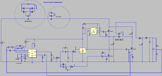
I've been told TR1 and TR2 in the picture I posed; are normally driven on simultaneously by applying a positive gate-source voltage to each of them.
As seen in the picture though; driving the lower device, TR2, directly from a low-voltage control IC connected to 0 V is relatively straightforward.
However, there is a difficulty with driving the upper device, TR1, as its source voltage swings between 0 V and 48 V. TR1 therefore cannot be driven directly from the output terminal of a low-voltage control IC connected to 0 V.
Explain how circuitry using a bootstrap diode, flying capacitor, high-voltage level-shifting MOSFET and a driver IC can be incorporated to enable TR1 to be driven from the low-voltage control circuitry.
Can anyone help me draw a diagram for this? I'm losing my mind over this question!