Venkadesh_M
Advanced Member level 4
- Joined
- Jun 26, 2013
- Messages
- 1,374
- Helped
- 258
- Reputation
- 516
- Reaction score
- 254
- Trophy points
- 1,363
- Location
- Coimbatore, India
- Activity points
- 8,019
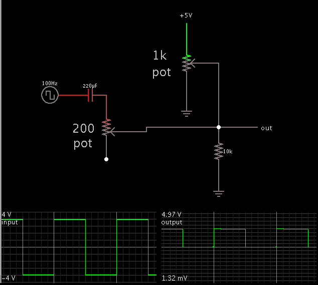
A combination of potentiometers can do this. One potentiometer conveys a portion of a 5V supply V.
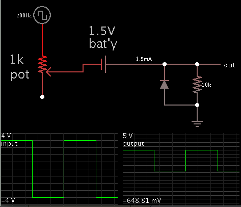
The capacitor blocks DC from flowing back toward your input signal. However the capacitor can distort a square waveform.
BradtheRod this not seem to work in all frequencies...... Isnt it??
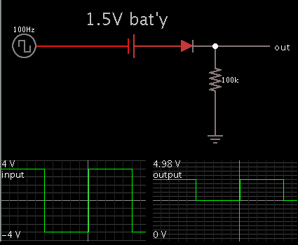
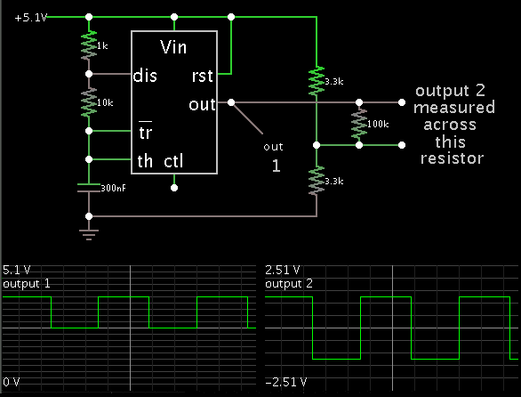
Try this