Continue to Site

Welcome to EDAboard.com

Welcome to our site! EDAboard.com is an international Electronics Discussion Forum focused on EDA software, circuits, schematics, books, theory, papers, asic, pld, 8051, DSP, Network, RF, Analog Design, PCB, Service Manuals... and a whole lot more! To participate you need to register. Registration is free. Click here to register now.

Dual band GSM Antenna

Status
Not open for further replies.

Ow@i$

Advanced Member level 1
Joined
Sep 18, 2012
Messages
413
Helped
78
Reputation
156
Reaction score
75
Trophy points
1,308
Location
Pakistan
Visit site
Activity points
3,430
Hey,
can anyone recommend a tested but compact GSM antenna for bands 900MHz and 1800MHz?
I need to design one immediately.
Thanks
 

Wide band staff. Probably @ same way for 900-1800MHz.
 

Attachments

  • Snap1.jpg
    Snap1.jpg
    100.6 KB · Views: 131

Can you provide us more info:
-Maximum size/volume,
-antenna near metal plane or edge,
-Ground plan available,
-maximum VSWR,
-available materials and production method,
etc.

Be prepared that when the size/volume becomes small (with respect to 0.25 wavelength), you will not get the required bandwidth without adding additional radiating or non-radiating resonating structures.

Regarding "immediately", antennas having more then one resonating structure for each band are relatively complicated.
 

@WimRFP
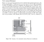
I have attached a doc, it is a quad-band GSM Antenna by Taoglas Ltd. I have to design this type of Antenna, with close resemblance both in Physical Dimensions wise as well as in terms of its technical specs. What I don't have is a exact shape & Dimensions of the Conductive Area. So I was thinking if someone with design experience in this stuff can guide me through!!
Thanks
 

Attachments

  • PC27.09.0100A Quad-Band GSM PCB Antenna 290110.pdf
    1,022.2 KB · Views: 144

The low band (800/900) looks like a single resonant design. The high band looks like a two resonator structure, however that may also be caused by radiation from the feed line's braid.

I did a google images search with: dual band GSM antenna design, scroll down and you will find PCB pictures of several of such antennas. When having some design ideas, you should ask yourself is your design to learn something about antennas or just show something that functions?
 

well I agree about learning but frankly speaking when you have to deliver in short time one tends to design and fabricate a existing tested model rather indulging in basics which is no doubt great and one should do but gets difficult to do in short time.

I have done that searching before but as i said compact design with dimensions and results!! I didn't find any. I Found out some good designs like **broken link removed**but the size is unacceptable to the client !!
 

Besides VSWR, did you (or your client) also look to the average gain and or radiation efficiency? Most of my clients would not accept the values stated in the datasheet.

Other things:
Does your client use the antenna as showed in the datasheet? When you place it close to a conducting plane/edge, VSWR curves will change significantly.

When the antenna uses the coaxial cable's braid at the low band, cable routing will affect VSWR and radiation pattern.


If you really want this antenna fast, try to get one (or a similar one). When you look to the VSWR at low band it is narrow band. Changes in FR4 laminate rel. epsilon may shift the resonance out of your desired frequency range. Just copying the layout may not give you the desired result.
 

Mobile Antenna Systems Handbook (Artech House Antennas and Propagation Library)
3rd edition, chapter 5.2.2.3
 

Well Thanks WimRFP!!! indeed parameters other than layout does effect the results.
As a matter of fact I am designing in ADS 2009, the Antenna in the Doc that I have attached in the previous post (**broken link removed**). But I am not achieving the desired result possibly due to some error in configuring the stackup or ports or something. I have attached the project, I would really appreciate if you can just have a look at it and tell me where I am possibly wrong. It is actually my first Antenna design and i have read that not only the physical layout but configuring the software for the antenna is also important, to achieve the desired result.
Thanks!!
waiting for ur response
 

Attachments

  • GSM_Dual_Band_Antenna_prj.zip
    243.7 KB · Views: 124

@volker@muehlhaus
Could you plz upload the updated design. and you didn't change anything else right? because i am kinda not getting graph as you are.
 

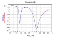
@Ow@i$: I don't have ADS, so I can't support you with ADS software related issues.The RL graph in Volker's posting looks good.

Is the ground plane around the CPW structure present in the actual situation (as the antenna in your posting #4 don't have such large ground plane/ counterpoise)?
 

Actual ??? yeah I mean the doc says so to have ground patch on both side of the CPW, regarding the one in post#4 yes it don't has that big ground but i have read somewhere that ground should be about 0.25λ that makes the second antenna quite comparatively big!!!
well could you tell what loss-tangent value should I keep for FR4 in my dual band, I saw people using different values and I have seen in the simulation if i change the value slightly the result changes.
 

Typically two bands not enough. Should be triple + 3G ~ 2.1GHz as well. Depend from region.
 

Could you plz upload the updated design.

I used ADS2012 that has the new OA database, so you can't open my files in ADS2009.

and you didn't change anything else right? because i am kinda not getting graph as you are.

- Updated substrate as shown
- Added bridge as shown
- Simulated with port calibration OFF (!)

could you tell what loss-tangent value should I keep for FR4 in my dual band

I didn't change your FR4 material definition.
tand=0.02 ... 0.03 would be a good estimate
 

@Ow@i$: You can design whatever antenna you want, but when you don't know how it is used, the actual design time will be long as you may need to start all over again.

Just an example: you use a large ground plane. Monopoles like large ground planes (as a substitute for the other half normally present in a dipole). I you don't have a ground plane (for example because of connection via a cable), you need to include the cable braid into the simulation. If so, you need to change to a lumped (localized) port scheme.

When the antenna is close to a dielectric structure, you need to include that structure into the simulation. The effect of nearby metallic structures is even more severe.
 

Status
Not open for further replies.

Part and Inventory Search

Welcome to EDABoard.com

Sponsor

Back
Top