Continue to Site

Welcome to EDAboard.com

Welcome to our site! EDAboard.com is an international Electronics Discussion Forum focused on EDA software, circuits, schematics, books, theory, papers, asic, pld, 8051, DSP, Network, RF, Analog Design, PCB, Service Manuals... and a whole lot more! To participate you need to register. Registration is free. Click here to register now.

DS1307 RTC Power Problem When Unplugging Adapter

Saeedk9574

Junior Member level 3
Joined
Nov 6, 2023
Messages
31
Helped
0
Reputation
0
Reaction score
0
Trophy points
6
Activity points
215
Hi everyone,
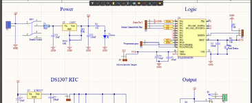
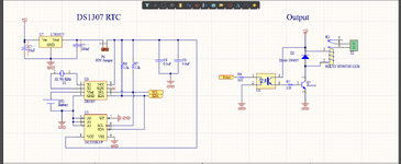
I have gotten a strange problem with my circuit. Ac you can see in schematic this a timer RTC with DS1307. In the absence of power supply, ds1307 works with coin battery.
Here I use a 12v adapter as power supply, This 12v is decreased with lm317 regulator to 3.3 for microcontroller and it is also decreased to 5v with a l7805 regulator for ds1307 RTC.
The strange problem is when I disconnect 12v adapter from wall-plug, RTC works with battery and can save time (12v adapter is connected to the board but disconnected from wall-plug )
But when I disconnect the board from 12v adapter RTC does not work and it gets reset when I connect it again to 12v.

I hope you understand what the problem is. Apparently, there is a circuit inside 12v adapter that can affect the board even though it is not connected to the outlet.


Wall-plug-----(disconnect from here)------12v adapter ------------------------------------ board =====>> it works
Wall-plug------------------------------------12v adapter---(disconnect from here)-------- board =====>> it does not works
 

Attachments

  • Screenshot (188).png
    Screenshot (188).png
    140.1 KB · Views: 68
  • Screenshot (189).png
    Screenshot (189).png
    110.9 KB · Views: 65
Two points to check:

1. the I2C pull-up resistors connect to 5V but the MCU is powered from 3.3V so logic high may be excessive for the MCU, better to tie them to a 3.3V supply.
2. The recommended output load resistor (R3) on the LM317 is 240 Ohms, with a higher value you might get some voltage overshoot as it powers up or the load significantly changes.

I would also suggest adding a diode between the input and output pins of both regulators, cathode end to the input, especially on U2 to prevent charge on C2 causing reverse voltage as the input is switched off.

Brian.
 
1. the I2C pull-up resistors connect to 5V but the MCU is powered from 3.3V so logic high may be excessive for the MCU, better to tie them to a 3.3V supply.
Not only pull-up, also RTC is powered by 5V. Correct logic levels aren't guaranteed with mixed voltage design. I also notice that MCU supply can be switched off while 5V is maintained. Bad idea, asking for trouble.

To understand what's happening in your special test, you can monitor 3.3V and 5V rail. Common 3.3V supply is required anyway.
 
Two points to check:

1. the I2C pull-up resistors connect to 5V but the MCU is powered from 3.3V so logic high may be excessive for the MCU, better to tie them to a 3.3V supply.
2. The recommended output load resistor (R3) on the LM317 is 240 Ohms, with a higher value you might get some voltage overshoot as it powers up or the load significantly changes.

I would also suggest adding a diode between the input and output pins of both regulators, cathode end to the input, especially on U2 to prevent charge on C2 causing reverse voltage as the input is switched off.

Brian.
I applied these changes including changing pullup resistors to 3v3 and putting diodes for regulators. but nothing has changed and the problem is not solved. I guess there is a filter problem in MCU and RTC. However, you can see I have used filter capacitors for both MCU and RTC.
--- Updated ---

Hi,

read this: https://www.edaboard.com/threads/questions-and-problems-by-ds1307-rtc.409617/post-1766763

Same situation with the ESD diodes, but now it´s the diode(s) inside the microcontroller.

Klaus
Changing diodes and pull-up resistors did not solve the problem.
--- Updated ---

Not only pull-up, also RTC is powered by 5V. Correct logic levels aren't guaranteed with mixed voltage design. I also notice that MCU supply can be switched off while 5V is maintained. Bad idea, asking for trouble.

To understand what's happening in your special test, you can monitor 3.3V and 5V rail. Common 3.3V supply is required anyway.
DS1307 RTC needs 5v and when it drops Vbat x 1.25 it switches automatically to Vbat(3v). accordingly 5v is necessary. here is the explanation of datasheet in this case:

OPERATION
The DS1307 operates as a slave device on the serial bus. Access is obtained by implementing a START
condition and providing a device identification code followed by a register address. Subsequent registers
can be accessed sequentially until a STOP condition is executed. When VCC falls below 1.25 x VBAT the
device terminates an access in progress and resets the device address counter. Inputs to the device will
not be recognized at this time to prevent erroneous data from being written to the device from an out of
tolerance system. When VCC falls below VBAT the device switches into a low-current battery backup
mode. Upon power-up, the device switches from battery to VCC when VCC is greater than VBAT + 0.2V
and recognizes inputs when VCC is greater than 1.25 x VBAT. The block diagram in Figure 1 shows the
main elements of the serial RTC.
 
Last edited:
Hi,

Changing diodes and pull-up resistors did not solve the problem.
You did change the ESD diodes? How? Removed the IC plastics, got access to the silicon die and rmeoved the diodes?
It´s working in the nanometer sizes. I doubt it.

Klaus
 
I had heard of this problem from a sub-contractor long ago. I forget the solution.
I sense it is a difference in the -dV/dt with a dry contact removal of DC vs AC slower rate of change with possible bounce. Thus parasitic C and ESR will affect the Vcc vs Vbat ref detection of state change. This suggests filtering should improve the result.
 
I still guess its a 5V vs. 3.3V problem and ESD diodes are conducting to pull the supply up or down. Directly connecting devices that use different supply voltages is always a problem, perhaps a level translator would be a better solution. You can but cheap level converters or make your own with just a few components. For example:
https://www.amazon.co.uk/Teyleten-R....3v+5v+level+converter&qid=1706459398&sr=8-29 but note the price is for 10 boards, you can get singles of course.

Brian.
 
DS1307 RTC needs 5v and when it drops Vbat x 1.25 it switches automatically to Vbat(3v).
Do you understand that it´s a problem with the signal lines SDA and SCL?

You may power your DS1303 with 5V - no problem.
But pulling the SDA and SCL to 5V is the problem .. because is clearly violates microcontroller signal input levels.

If you look into the DS1307 datasheet: it says the DS1307 is happy with signal levels of 3.3V. Indeed it says VIH > 2.2V.

--> pull the SDA and SCL up to 3.3V (not 5V)
This solves at least one problem... not necessarily all problems.

Klaus
 
I had heard of this problem from a sub-contractor long ago. I forget the solution.
I sense it is a difference in the -dV/dt with a dry contact removal of DC vs AC slower rate of change with possible bounce. Thus parasitic C and ESR will affect the Vcc vs Vbat ref detection of state change. This suggests filtering should improve the result.
I have used bypass capacitors for MCU and RTC. Which types of filters can I use?
 
Hi,

did you read the microcontroller datasheet:
" VDDA = from V DD to 3.6 V: external analog power supply for ADC, Reset blocks, RCs
and PLL. The VDDA voltage level must be always greater or equal to the V DD voltage
level and must be provided first.
"

It seems you did not care about this.
 
Do you understand that it´s a problem with the signal lines SDA and SCL?

You may power your DS1303 with 5V - no problem.
But pulling the SDA and SCL to 5V is the problem .. because is clearly violates microcontroller signal input levels.

If you look into the DS1307 datasheet: it says the DS1307 is happy with signal levels of 3.3V. Indeed it says VIH > 2.2V.

--> pull the SDA and SCL up to 3.3V (not 5V)
This solves at least one problem... not necessarily all problems.

Klaus
As I mentioned I have already changed them to 3.3 but the problem still remained. If you had any other Idea I would be happy to hear.
--- Updated ---

Hi,

did you read the microcontroller datasheet:
" VDDA = from V DD to 3.6 V: external analog power supply for ADC, Reset blocks, RCs
and PLL. The VDDA voltage level must be always greater or equal to the V DD voltage
level and must be provided first.
"

It seems you did not care about this.
OMG!!!! I connected the both VDD and VDDA to the same 3.3v, but I provided VDD first then a track from VDD to VDDA. By this explanation after reconnecting 12v power supply MCU gets reset because VDD is provided first then VDDA. Am I right????!!!!
 
Last edited:

LaTeX Commands Quick-Menu:

Similar threads

Part and Inventory Search

Welcome to EDABoard.com

Sponsor

Back
Top