Continue to Site

Welcome to EDAboard.com

Welcome to our site! EDAboard.com is an international Electronics Discussion Forum focused on EDA software, circuits, schematics, books, theory, papers, asic, pld, 8051, DSP, Network, RF, Analog Design, PCB, Service Manuals... and a whole lot more! To participate you need to register. Registration is free. Click here to register now.

Driving mosfet in battery balancing circuit by an mcu

Status
Not open for further replies.

Jabar

Newbie level 3
Joined
Mar 16, 2016
Messages
3
Helped
0
Reputation
0
Reaction score
0
Trophy points
1
Activity points
32
Hi All,

I'm trying to make a simple passive battery balancing circuit using logic level n-mosfet driven by MCU. However, I've got some issue on how to drive the mosfets by the digital output of the mcu, and also having isolation between mcu ground and the source legs of the mosfet. Otherwise, in the case of the following circuit, the 2nd battery would be short circuited.
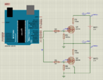
balancing.PNG

Looking forward to hear your thoughts or maybe another alternative to drive the mosfet. I was thinking to use optocoupler, but then I need another isolated supply. Thanks
 

Hi,

The GND symbols at R3 and R6 create a short circuit to BAT2.
At least one of them needs to be disconnected.

I'd use the GND at the lowest voltage, this also must be the GND of the microcontroller.
Then use a low_side / high_side driver for the Mosfets.

Klaus
 

An opto isolator should do the trick.
Connect the phototransistor between gate and +3.7v from the battery.
Opto isolator turns on, and that hopefully turns on the mosfet.

I am looking at doing something similar, but have great reservations about having enough gate voltage to get the mosfet to turn on properly.
A bipolar transistor or darlington would be much better at these low voltages.
 

Hi,

The GND symbols at R3 and R6 create a short circuit to BAT2.
At least one of them needs to be disconnected.

I'd use the GND at the lowest voltage, this also must be the GND of the microcontroller.
Then use a low_side / high_side driver for the Mosfets.

Klaus

Hi Klaus,

thanks for your comment. That was the problem, I was intentionally put the ground to drive the mosfet. But for this configuration, it would create a short circuit. If I put the GND only the lowest voltage, the mosfet at the top would not switch, since it is not referenced to the MCU's ground. I'm looking for kind of driving "floating" mosfet.
 

An opto isolator should do the trick.
Connect the phototransistor between gate and +3.7v from the battery.
Opto isolator turns on, and that hopefully turns on the mosfet.

I am looking at doing something similar, but have great reservations about having enough gate voltage to get the mosfet to turn on properly.
A bipolar transistor or darlington would be much better at these low voltages.

Hi Tony,

that is a great idea, but I would have to find a mosfet that has vgs lower than the battery voltage. It might be really helpful if you have some references implementing this using bipolar transistor or darlington. thanks.
 

The mosfet you selected does have a fairly low gate threshold, I did look it up earlier, I think from memory it was 1.8 volts.
It would certainly work in your circuit, but I think a bipolar transistor would be a better choice for this application.

Its getting late here now.

Tomorrow morning I will see what I can find for a suitable opto and bipolar transistor. That should not be difficult.
It only has to sink 370mA which is not a lot.
 

Hi,

i don´t think a darlington has improvements... but it all depends on the specifications..
like current, switching frequency....

Klaus
 

To correctly balance-charge a lithium battery then instead of re-inventing the wheel and possibly causing a few fires and explosions why don't you use a lithium charger IC made for balance-charging a lithium battery??
Or is this school work? When I was young I survived school work since I still have all my fingers.
 

O/K back again.

I looked at a few bipolar transistors, but the problem there is to get a device that will safely carry 370mA requires a fairly large physical package.
The BSS138 safe operating area only allows 100 mA maximum, so its far too small.

Its really overkill, but something like this would work:
https://www.onsemi.com/pub_link/Collateral/NTGS3446-D.PDF
Logic level mosfet, gate threshold less than 1.2v, surface mount, and it will carry plenty of current.

With a 10K pull down resistor on the gate, any common direct photo transistor output opto isolator would then work. The CNY17 is available in surface mount is pretty typical.
https://www.vishay.com/docs/83606/cny17.pdf
Figure 7 says it will have about 0.1v drop at the very low output current we require.

These are just examples of components that would work, there is a pretty wide choice of similar alternatives out there.

Just be aware that your ten ohm resistor must dissipate around 1.4 watts which will require a fairly large resistor if the temperature rise is to be kept reasonable.
 

Status
Not open for further replies.

Similar threads

Part and Inventory Search

Welcome to EDABoard.com

Sponsor

Back
Top