Continue to Site

Welcome to EDAboard.com

Welcome to our site! EDAboard.com is an international Electronics Discussion Forum focused on EDA software, circuits, schematics, books, theory, papers, asic, pld, 8051, DSP, Network, RF, Analog Design, PCB, Service Manuals... and a whole lot more! To participate you need to register. Registration is free. Click here to register now.

Driving LED with multiple input voltages

Status
Not open for further replies.

tiwari.sachin

Full Member level 6
Joined
Aug 1, 2009
Messages
341
Helped
3
Reputation
6
Reaction score
3
Trophy points
1,298
Location
India
Activity points
4,449
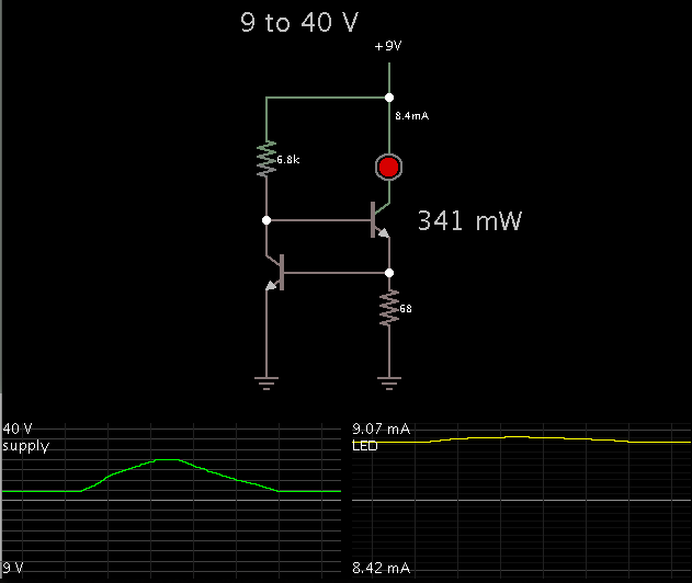
I have been trying to wrap my mind around this one for quite some time now... I need to drive a opto isolator and the input voltages can change from 9V to 30V. The output ofcourse goes to a controller pin.

How can I design the current limiting resistor in such a scenario.

Are there any better options to achieve the same result without use of opto isolator.

- - - Updated - - -

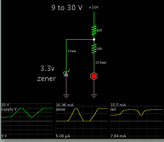
cant i just use a 5v or 3.3v zener at the input. How effective and reliable would this be. How to calculate, upto what voltage inputs, the zener gonna work.
 

Yes, a zener will do the job.

Here is a simulation. Values were adjusted so that neither the zener or led are exposed to greater than 20 mA.


There is another method to limit current, by using two transistors and a resistor or two.
 
  • Like
Reactions: tpetar

    tpetar

    Points: 2
    Helpful Answer Positive Rating
What is the program for simulation ?

Yes, a zener will do the job.

Here is a simulation. Values were adjusted so that neither the zener or led are exposed to greater than 20 mA.


There is another method to limit current, by using two transistors and a resistor or two.
 

This is Falstad's simulator at falstad.com/circuit.

It's a free download. It comes with a library of circuits.

It can export a link containing an entire simulation. The link below will open the Falstad.com website, load my schematic above, and run it on your computer.

https://tinyurl.com/btlnb8x

You can alter values by right-clicking on a component, and select Edit.

- - - Updated - - -

At the extreme right you'll see a slider with the label 'Supply voltage'. It's set for a range of 9 to 30V. That's the interactive part of the simulation. You can see what happens in all situations over the entire range.
 

Be careful with using a zener though. The diode is a stabilizer, it conducts when it reaches it's threshold and the excess voltage / current must be dropped by the feed resistor or the diode will burn out. You can drop a lot of power this way if you are not careful.
Another way is to use a transistor, sense resistor and two diodes to form a constant current source and set it the a low value that will provide a positive signal to the opto LED (like 5 or 10 mA). This can reduce the power heating due to the increase in resistance at higher voltages (I2R)
 

BradtheRad... I tried the circuit with simulation and it works fine but I am not sure how reliable it would be.

tmd_63... Could to explain me exactly how I can use the option you say and how would that be helpful in the design.


"The input voltage ranges will be upto 40V and not 30V as said earlier". The product will be used in UAE and hence the temperature would be quite high and operating temperature (max) specified is around 85 deg.
 
Last edited:

BradtheRad... I tried the circuit with simulation and it works fine but I am not sure how reliable it would be.

"The input voltage ranges will be upto 40V and not 30V as said earlier". The product will be used in UAE and hence the temperature would be quite high and operating temperature (max) specified is around 85 deg.

Reliability problems can crop up because the dropping resistor must dissipate power as heat. Now with the maximum supply being 40V, the resistor has to be rated to carry 1.63 W. This can be reduced if you reduce current. However then the led will be dim when the supply is 9V.

As an alternate there are constant-current regulators, such as the two-transistor type. No need for a particular zener value.
You may see different configurations.
The one below seems to work. LED current is pretty much constant over the entire range of supply V.


(I thought I had posted a reply similar to this one, but I guess it was lost.)
 

Status
Not open for further replies.

Similar threads

Part and Inventory Search

Welcome to EDABoard.com

Sponsor

Back
Top