Continue to Site

Welcome to EDAboard.com

Welcome to our site! EDAboard.com is an international Electronics Discussion Forum focused on EDA software, circuits, schematics, books, theory, papers, asic, pld, 8051, DSP, Network, RF, Analog Design, PCB, Service Manuals... and a whole lot more! To participate you need to register. Registration is free. Click here to register now.

Driving an AC voltage digitally

Status
Not open for further replies.

bremenpl

Member level 3
Member level 3
Joined
Jan 5, 2013
Messages
63
Helped
0
Reputation
0
Reaction score
0
Trophy points
1,286
Visit site
Activity points
1,827
Hello there,
I have a problem Im not sure how to resolve.
I need to build a device that will drive a heating element powered from 230V AC (50Hz). I will take feedback from analog temp sensors. That way I could implement some PID alghorithm to controll the temperature and keep it steady. If this would be DC voltage on the heater I would simply drive FETS using PWM from the microcontroller. The problem is this is AC and the PWM would have to be synchronised.
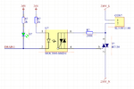
I have a circuit here that would work only for turning ON/OFF the Diacs controlling the heater. I am not sure how to sync my PWM signal with 50Hz AC frequency.
Windows 7 pro 32 bit-2014-10-13-14-54-59.png

I would really aprichiate any help in this matter. I need to know how can I smoothly controll the temp this way. I believe light dimmers work simmilar way.
 

hi,
When you say PWM control do you mean 'phase time On control'.?
Your MOC has already got zero cycle detection.

Have you considered simple 'burst' control of the heater, ie: on for so many cycles , then off
E
 

That is also what someone else suggested me elsewhere. I need to add an additional zero detecot that can give feedback to mcu. Then i will count the cycles like you suggested.
 

The ZCD in your MOC will automatically switch at the zero crossing point, if your MOC drive is high, whatever the state the 50Hz cycle is in.

So apply a short High [ as determined by your PID controller ] to the MOC control signal input and the MOC will enable the Triac at zero crossing.
E
 

Attachments

  • AAesp04.gif
    AAesp04.gif
    11 KB · Views: 98

This circuit doesnt give me feedback on when the triac turns off. I turn it on and it will turn off when crossing zero if i wont light the led. But i wont know either it happened or not. This circut only enables me to burst the triac. I need something like SFH620. Its a dual led optocoupler with open drain output. Everytime a zero is crossed i get a pulse.

At least i think it works this way. The way you explained it it would seem that zero crossing enables the triac.
 

For a resistive load like heater the triac will be automatically turned off when crossing zero.

If you want to ensure that, you can have the input of currnt signal or voltage across thyristor, but i don think its important to do so.

The temperature control will take care of it.
 

But Incant let thevtwml take care of it. I needntp countvexacly for how long will thebtriac staynon. Thisbhas to beba very precise system.
 

But I cant let the temp take care of it. I need to count exactly for how long will the triac stay on. This hast be a very precise system.

Then you need to take a current sample or voltage sample across triac, give it to zero comparator and invert the output.
If there is no high pulse on the output then the triac is continiously ON.
 
you need a zero crossing circuit like this.
**broken link removed**
it will give your controller a signal at every zero value of your sine wave.
then you need to program your controller for firing of thyristor.
zero crossing will raise after every 10ms. Its mean you have 10ms time between two zero crossings.
now you need your micro controller to program to control heat.
you need to give a pulse to moc for firing. it would be max 100us.
this pulse will fire thyristor and thyristor will stay switch on while current is grater then thyristor holding current .
in next round you will again repeat this process .
if you want to control heat then your firing timing will decide for heating value.
if you fire after 1ms of zero crossing then heater will turn on for 9ms.
if you fire after 3ms of zero crossing then heater will turn on for 7ms.
if you fire after 5ms of zero crossing then heater will turn on for 5ms.

Sir Tahmid's has explained this problem and its solution in detail.
see this link .
https://tahmidmc.blogspot.com/2013/06/power-control-with-thyristor-phase.html
 

Status
Not open for further replies.

Similar threads

Part and Inventory Search

Welcome to EDABoard.com

Sponsor

Back
Top