Continue to Site

Welcome to EDAboard.com

Welcome to our site! EDAboard.com is an international Electronics Discussion Forum focused on EDA software, circuits, schematics, books, theory, papers, asic, pld, 8051, DSP, Network, RF, Analog Design, PCB, Service Manuals... and a whole lot more! To participate you need to register. Registration is free. Click here to register now.

Driving a high current load from a CMOS level output

Status
Not open for further replies.

cgchas

Member level 3
Joined
Jul 19, 2011
Messages
56
Helped
2
Reputation
8
Reaction score
4
Trophy points
1,288
Activity points
2,001
I am considering the suitability of some components for driving a high current load from an IC chip.
The output of the IC is 5V with a maximum current of 25mA.

Description of the driven load:

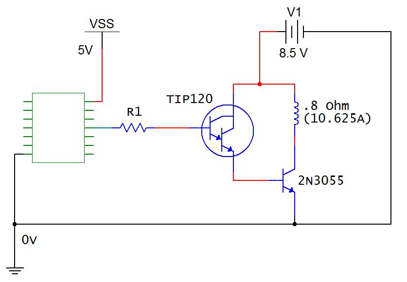
Supply Voltage: 8.5V
Load Resistance: .8 Ohms
Load Current: 10.625A

The driver components I am considering are TIP120 Darlington Transistor driving a 2N3055 Power Transistor. (image attached)

I am still learning how to calculate all of this so if possible I would like some help looking over my calculations.

Something I am not sure of is how to properly apply the datasheet information for Collector-Emitter Saturation Voltage for the TIP120. (see below)

My goal is to use the drivers as switches that will ultimately be pulsed so I want the base currents to be correct to assure saturation. For now, let's
assume no pulsing.

2N3055 Power Transistor

max collector current: 15A
max base current: 7A
min hFE: 5
base current for saturation with 15A at collector: 15/5 = 3A

collector current for driving the load: 10.625A
base current for saturation: 10.625/5 = 2.125A

TIP120 Darlington Transistor

max collector current: 5A
max base current: 120mA
minimum hFE at saturation: 250
base current for saturation with 5A at collector: 5/250 = 20mA

assuming collector current for driving the 2N3055: 2.125A
base current for saturation: 2.125/250 = 8.5mA

assuming collector current for driving the 2N3055: 3A
base current for saturation: 3/250 = 12mA

R1 (IC output to TIP120 base)

TIP120 saturation voltage at 3A: 2V
for 8.5mA base: R1 = (5v - 2V) / .0085 = 352.94 Ohms
for 12mA base: R1 = (5v - 2V) / .012 = 250 Ohms

I treated the 2V saturation voltage as a voltage drop off the IC output. Was I correct to do this?

Please advise regarding any of my assumptions.

Thank you,
Charles


There are two important things missing in your circuit:
- a current limiting means for the the TIP120, e.g a collector resistor
- a free wheeling diode for the coil

The unpleasant point is, that you need to drive the maximum required base current to the 2N3055 (which you calculated as 2.1 A) despite of the actual current gain and burn about 17 W in the current limiting resistor and TIP120. The only solution to avoid this is using an output transistor with higher minmal gain. State of the art solution would be a MOSFET switch.
 
  • Like
Reactions: cgchas

    cgchas

    Points: 2
    Helpful Answer Positive Rating
There are many MOSFETs that can switch the current you show with just 5 volts driving the gate. What frequency will you be pulsing the final circuit.
 
  • Like
Reactions: cgchas

    cgchas

    Points: 2
    Helpful Answer Positive Rating
There are two important things missing in your circuit:
- a current limiting means for the the TIP120, e.g a collector resistor
- a free wheeling diode for the coil

The unpleasant point is, that you need to drive the maximum required base current to the 2N3055 (which you calculated as 2.1 A) despite of the actual current gain and burn about 17 W in the current limiting resistor and TIP120. The only solution to avoid this is using an output transistor with higher minmal gain. State of the art solution would be a MOSFET switch.

Regarding the diode, the actual circuit with the coil has a diode for protection from the voltage spike on field collapse.

I am trying to fully understood the rest of your answer.

The TIP120 and 2N3055 are an arbitrary selection that I am using as an exercise to gain a firmer grasp on how to do the calculations that show why the selected components will or will not work.

That said, could I trouble you to be a bit more elaborate with your answer, specifically how do you arrive at the needed resistance value for limiting the current at the collector-emitter circuit of the TIP120, when the emitter is connected to the 2N3055 base? and how are you arriving at the 17W dissipation?

---------- Post added at 20:33 ---------- Previous post was at 20:21 ----------

DeLorean
There are many MOSFETs that can switch the current you show with just 5 volts driving the gate. What frequency will you be pulsing the final circuit.
Perhaps 1-2 KHz. Please feel free to recommend any devices, but I also I want to gain a better understanding of how to properly calculate for use of the BJT drivers and fully understand their limiting factors for the circuit I have described.

---------- Post added at 20:45 ---------- Previous post was at 20:33 ----------

Just a guess as to where you are coming up with the 17 Watt dissipation.
If I placed a 4 ohm resistor between the TIP120 emitter and 2N3055 base:

8.5V / 2.125A = 4 Ohms
P = 2.125^2 * 4 = 18.06 Watts.

Is this what you mean?
 
Last edited:

Perhaps 1-2 KHz. Please feel free to recommend any devices, but I also I want to gain a better understanding of how to properly calculate for use of the BJT drivers and fully understand their limiting factors for the circuit I have described.

I use IRLB3034 for all my high power driving. Look at the data sheet and you will see that 5 volts on the gate will get you a very low turn on resistance.
 
  • Like
Reactions: cgchas

    cgchas

    Points: 2
    Helpful Answer Positive Rating
Just a guess as to where you are coming up with the 17 Watt dissipation.
If I placed a 4 ohm resistor between the TIP120 emitter and 2N3055 base:

8.5V / 2.125A = 4 Ohms
P = 2.125^2 * 4 = 18.06 Watts.

Is this what you mean?
If you review my post, you'll notice that I've been talking about a collector resistor.

But you basically go the calculation. The more interesting question is, what happens without this resistor. Because all calculations are based on minimal ("assured") current gain numbers, the TIP120 current will be considerably higher than 2 A and mostly dissipated in the transistor. It will quickly blow the TIP120 and the 2N3055 as well.

You have of course the other option to connect the TIP120 collector to the 2N3055 collector instead of the battery. In this case, you get a high saturation voltage of the output transistor and excessive losses as well. This is a basic issue of bipolar transistor power switches that can't be easily overcome.

I understand, that there may be a motivation to use cheap BJT power transistors that can be purchased for some 10 cents or a few rupies around the corner. But then you have to deal with the circuit compomises of last centuries electronics.
 
  • Like
Reactions: cgchas

    cgchas

    Points: 2
    Helpful Answer Positive Rating
If you review my post, you'll notice that I've been talking about a collector resistor.

But you basically go the calculation. The more interesting question is, what happens without this resistor. Because all calculations are based on minimal ("assured") current gain numbers, the TIP120 current will be considerably higher than 2 A and mostly dissipated in the transistor. It will quickly blow the TIP120 and the 2N3055 as well.

You have of course the other option to connect the TIP120 collector to the 2N3055 collector instead of the battery. In this case, you get a high saturation voltage of the output transistor and excessive losses as well. This is a basic issue of bipolar transistor power switches that can't be easily overcome.

I understand, that there may be a motivation to use cheap BJT power transistors that can be purchased for some 10 cents or a few rupies around the corner. But then you have to deal with the circuit compomises of last centuries electronics.

Cost is always a factor, but I assure you that the motivation for this stage of the project is getting a handle on applying the datasheet to proper calculations.

So if the goal was to get 10 Amps to the coil, and a significant amount of power was dissipated in order to do so (25% give or take), it would be inefficient by today's standards. Fair enough. This isn't a commercial product I am developing. It is more of an analysis of a coil's output in field strength for varying power input (this stage) as well as pulse frequency and duration (next stage).

Now if you come back and say that not only are BJT's inefficient for switching with regards to power dissipation AND they generally are as equally ineffective for switching high currents at high frequencies, then I will stop now and move onto MOSFET's. The only reason I have not done so already is that I am far less familiar with MOSFET specifications than I am BJT's. I realize that is a poor excuse, but time is the greatest motivation of all.

Thank you for your replies.
 

If switching speed is an objective, you also have to care for base-emitter resistors for faster turn-off. You should specify "high frequency" in terms of current rise and fall time, but I guess, it will be limited by the coil inductance rather than transistor speed. You most likely need to replace the coil with a resistive load to see the transistor speed.

I didn't want to say that it isn't feasible to use BJT. My reference to "last centuries electronics" also involves the fact, that it had good results for decades.
 
  • Like
Reactions: cgchas

    cgchas

    Points: 2
    Helpful Answer Positive Rating
If switching speed is an objective, you also have to care for base-emitter resistors for faster turn-off. You should specify "high frequency" in terms of current rise and fall time, but I guess, it will be limited by the coil inductance rather than transistor speed. You most likely need to replace the coil with a resistive load to see the transistor speed.

I didn't want to say that it isn't feasible to use BJT. My reference to "last centuries electronics" also involves the fact, that it had good results for decades.
The resistive load is actually what I am setting up initially to look at the wave form on a scope to see that the output looks right. Regarding the base-emitter resistors for faster turn-off, should I assume you mean in addition to a collector limiting resistor. If so, what value do you suggest for faster turn-off?
 

Status
Not open for further replies.

Part and Inventory Search

Welcome to EDABoard.com

Sponsor

Back
Top