mcmsat13
Member level 5

- Joined
- Apr 24, 2013
- Messages
- 94
- Helped
- 4
- Reputation
- 8
- Reaction score
- 4
- Trophy points
- 1,288
- Activity points
- 2,292
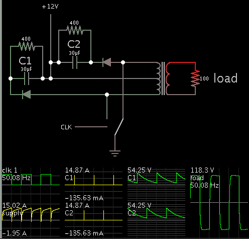
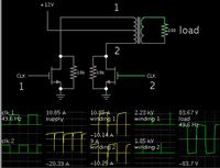
I have two identical diagrams here with the placement of the drain/source diode and RC snuber filter, the only difference. I like presenting my question with a diagram because it makes the question a visual subject. These diagrams are for reference purposes only.
When I using a switch module, MOSFET/IGBT, because they are a kind of single device, you place one single diode across the drain and the source likewise a single RC Snuber circuit.
Now, when using multiple descrete devices in parallel, must the Drain/Source diode and the RC Snuber soldered across each individual device? Some people have asked me this question and I have no better answer for them because I lack full explanation to this theory.

Now my question is:
Is the circuit "A" the correct one or the circuit "B"?
Please I need full/fair explanation here as answering me "A" or "B" alone will not make much difference in my learning.
When I using a switch module, MOSFET/IGBT, because they are a kind of single device, you place one single diode across the drain and the source likewise a single RC Snuber circuit.
Now, when using multiple descrete devices in parallel, must the Drain/Source diode and the RC Snuber soldered across each individual device? Some people have asked me this question and I have no better answer for them because I lack full explanation to this theory.

Now my question is:
Is the circuit "A" the correct one or the circuit "B"?
Please I need full/fair explanation here as answering me "A" or "B" alone will not make much difference in my learning.


