LvW
Advanced Member level 6
I must confess that I am able to observe a phase difference between a sinusoidal input voltage at the base and the amplified signal at the collector terminal of a common emitter configuration.
Follow along with the video below to see how to install our site as a web app on your home screen.
Note: This feature may not be available in some browsers.
I am able to observe a phase difference ... et etc
Maybe I'll put a couple of diagrams together to deal visually with this particular matter.
I think the point Syncopator is making is that there is no time difference between the signals, one is an upside down but immediate copy of the other. We normally measure phase difference as being the delay between the same points on two versions of the same waveform and quantify it as a proportion of time shift relative to a whole cycle. It's an acedemic point, I think we all refer to inversion as 180 degrees out of phase even when there isn't a half cycle delay. It's one of those cases where language and technology have drifted apart but common understanding has kept us all thinking along the same lines.
Brian.
Discussion? There is no discussion Brian, the top and bottom signals are inverted. Nothing more, nothing less.The discussion is whether the top and bottom signals in your picture are actually phase shifted or inverted.
Most certainly not.In an inverter the signal is instantaneously mirrored in the X axis so there is no delay involved. So is it still shifted 180 degrees?
Of course, you are free to use your own definition for "phase difference" or "phase shift" ...
- and in the particular case under discussion I agree with you that the term "inversion" indeed is a bit more correct than "phase shift".
Finally, I am not quite sure if it is really an important and "an interesting topic" (as Brian thinks).
In fact, it is a discussion on definitions only, is it not?
Syncopator, one question (theoretical): In a textbook on mathematics there is a sentence "multiplying a sinusoid with -1 is identical to shift the phase by 180 deg." Right or wrong?
I didn't hear anyone say they are "the same thing".The fact it is, whether you like it or not and whether you accept it or not, that inversion is not the same thing as a phase shift, of 180° or any other angle.
It is quite wrong. Unfortunately, textbooks do carry errors. Many of them are because, through no fault of the author's, they are labouring under a misconception.
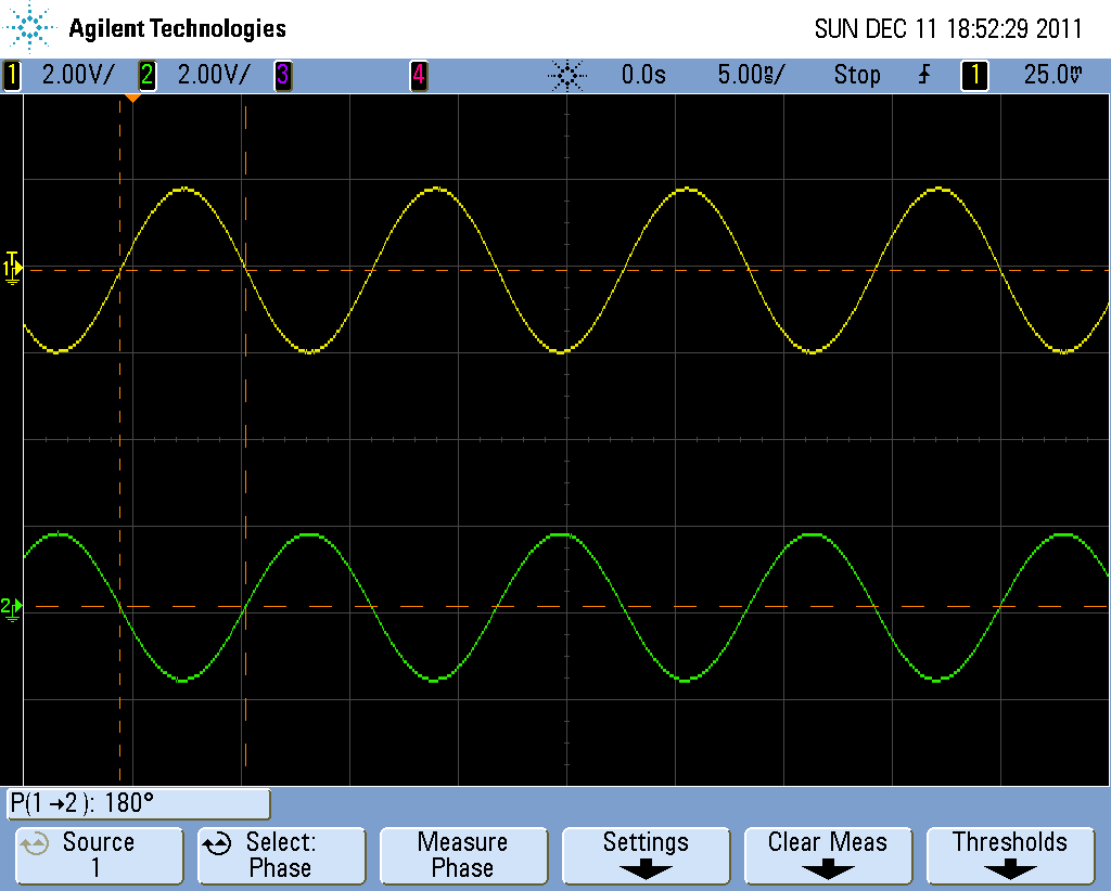
The below waveform continues my post #24. The problem is, that my oscilloscope doesn't display those enligthening red circles. But you surely can tell, if the 180° phase difference was generated by signal inversion or phase shift?
What's your point in deciding about configurations? If a circuit doesn't clearly implement a particular prototype, as e.g. the discussed transistor stage with two ouputs, there's nothing to decide.i also have same problems in deciding configuration of transistors in circuit.
please give your valuable views for deciding configurations of trasistors in circuits (digital or analog)
It is quite wrong. Unfortunately, textbooks do carry errors. Many of them are because, through no fault of the author's, they are labouring under a misconception. As I mentioined post #22 of this thread, if someone is taught incorrectlly, or, failing tuition, they pick up wrong information in forums or an other technical sites, they don't know any better, and the longer they harbour misconceptions the harder it is to correct them. Some of the never do.
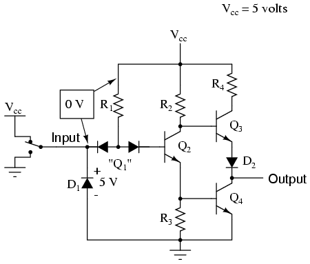
CB,CE,CC are for small signal analysis. YOu please bound with followers. Which terminal follows your output.hey guyz,in the diagram there is ttl not gate given.i wanted to know in which configuration(CB,CE,CC) is the transistor Q2 connected and how to determine that.