Continue to Site

Welcome to EDAboard.com

Welcome to our site! EDAboard.com is an international Electronics Discussion Forum focused on EDA software, circuits, schematics, books, theory, papers, asic, pld, 8051, DSP, Network, RF, Analog Design, PCB, Service Manuals... and a whole lot more! To participate you need to register. Registration is free. Click here to register now.

DOT-matrix display(LED matrix) points for a good design.

Status
Not open for further replies.
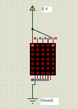
convert to led matrix

can someone help me design a sequential ckt of a scrolling message without using a microcontroller?? is it even possible??
 

dotmatrix shift

showstopper123 said:
can someone help me design a sequential ckt of a scrolling message without using a microcontroller?? is it even possible??

I believe it's possible but not worthly. Using a big eprom for storing the individual program steps with data bits and a clock driving address counter you can simulate what a small uC does. This willl be more complicated and expensive, and it's not so easy to determine the programming of the eprom.
Study the program steps of a PIC scrolling ckt (for example)!
zuisti
 

ebookee

I am trying to build an Infrared Transmitter and receiver that will take an RS-232 signal, convert it into TTL, then Pulse Width Modulation would be applied, and then finally transmitted. On the reciever side, basically extracting the orignal TTL signal from the Pulse Width Modulated signal and converting it back to RS-232.
Anyone can give me some guidance about this project?
 

current source ic for 8*8 dot matrix displays

yupng said:
I am trying to build an Infrared Transmitter and receiver that will take an RS-232 signal, convert it into TTL, then Pulse Width Modulation would be applied, and then finally transmitted. On the reciever side, basically extracting the orignal TTL signal from the Pulse Width Modulated signal and converting it back to RS-232.
Anyone can give me some guidance about this project?

What does this have to do with dot matrix displays?
 

*.asm proteus

blueroomelectronics said:
yupng said:
I am trying to build an Infrared Transmitter and receiver that will take an RS-232 signal, convert it into TTL, then Pulse Width Modulation would be applied, and then finally transmitted. On the reciever side, basically extracting the orignal TTL signal from the Pulse Width Modulated signal and converting it back to RS-232.
Anyone can give me some guidance about this project?

What does this have to do with dot matrix displays?

i had done a dot matrix display project which is using PC RS 232 port to send the data display device. I used cable to connect between RS 232 port and display device. Now i want change it to Infarad connection.
 

keyboard using dot matrix displays

Anyone know how to transmit the data using RS232 port with Infarad? No cable is used.
For Example:
i already built a dot-matrix display project which the data transfer from RS232 port to dot-matrix display device with using cable connect between them.
So now, no cable is used to transfer the data. Only transfer data wireless(any wireles type but prefer IR).
Anyone can teach me how 2 do it?

Pls HELP...............
 

led matrix + proteus

I am looking for a source of pc boards to drive dot matrix (led scrolling message). I need only the pc boards since we have our own led arrays.

Requirements:
40 columns okay but prefer 80 columns
USB interface to pc for loading messages
IR interface for loading messages

ray.phillips@articulux.com
 

how to drive an led display matrix.

Hey to everyone....i want built a "Wireless Announcement Board". I would like to use a PC to send the data out(using RS232 port) to Microcrontroller,the data(a word or character) will display on dot-matrix screen. I found many similiar project in this forum and most of the project using cable to connect RS232 port and microntroller. For me, i want to make it wireless(no cable is used to connect RS232 port and microntroller).
Anyone can help me? Pls.......
Anyone of u have a good idea for this "Wireless Announcement Board" beside the meathod i meantion.
 

Yes you can also use the GSM Modem SIM300 to send the data to MCU which can be displayed to DOT matrix Display
I am working on it
If some one have alredy done this please give me some precations

---------- Post added at 15:53 ---------- Previous post was at 15:51 ----------

In this case you will send the sms to the dot matrix display that will be received by SIM300. And MCU read that SMS and display the TEXT on the DOT matrix Display
 

hi.. good day to all of you.. may is 74HC595 multiplexer able to able to create a pattern like scroll up scroll down and other patterns in LED MATRIX DISPLAY. I have two lines of 5x8 LED MATRIX display.

---------- Post added at 14:23 ---------- Previous post was at 14:22 ----------

and one thing. Whats the most useful multiplexer for a LED MATRIX?

Yes i think you can do this by using two buttons
1 button for up and 2nd for down scrolling.
how many lines of data you want to display on the 2 lines of Dot matrix??
 
ImageShack® - Online Photo and Video Hosting

i want to ask the pin.outs of this 5x7 LED MATRIX.. why there is 7 pins up and down? what are those pin.outs?

7 Pins at one side are common cathode and 5 pins are anode pins.
If you connect the anode side of dot matrix and ground at cathode side then the corresponding leds will be glow. ie

if you connect ist pin of anode with Vcc and ist pin of cathode to the ground the LED on the Ist row and column will be glow.
As Seen in the Figure Below.....


thanks for the reply.. ^.^

anyway.. i was tasked to build 10x40 LED displays.. can you suggest what multiplexer should i used in column and rows? and can it drive 400 LEDS? with only 5v of supply? or can you suggest to increase my supply for about 12v?
 

Ist of all if you have found some thing helpful then click on the "Thanks " button instead of saying thanks.


thanks for the reply.. ^.^

anyway.. i was tasked to build 10x40 LED displays.. can you suggest what multiplexer should i used in column and rows? and can it drive 400 LEDS? with only 5v of supply? or can you suggest to increase my supply for about 12v?

*At the Anode end you can use shift registers "74HCT164" . with 330 ohm resistor for current limiting
*At the cathode end you can use 3to 8 multiplexir "74LS138" with darlington IC "ULN2803" for current increase.

It is just a good suggestion. Take a look for best solution at the internet.
 
Ist of all if you have found some thing helpful then click on the "Thanks " button instead of saying thanks.


*At the Anode end you can use shift registers "74HCT164" . with 330 ohm resistor for current limiting
*At the cathode end you can use 3to 8 multiplexir "74LS138" with darlington IC "ULN2803" for current increase.

It is just a good suggestion. Take a look for best solution at the internet.


thank you for the reply.. is it ok my Anode end is in ROW and my Cathode is in COLUMN? if i use 74HC595 or 74LST595AN in my COLUMN.. is it oK?
 

**broken link removed**

i want to ask if this is a good design for controlling LED MATRIX?

---------- Post added at 08:12 ---------- Previous post was at 08:04 ----------

Ist of all if you have found some thing helpful then click on the "Thanks " button instead of saying thanks.


*At the Anode end you can use shift registers "74HCT164" . with 330 ohm resistor for current limiting
*At the cathode end you can use 3to 8 multiplexir "74LS138" with darlington IC "ULN2803" for current increase.

It is just a good suggestion. Take a look for best solution at the internet.


sir you have schematic using this multiplexers?
 

thank you for the reply.. is it ok my Anode end is in ROW and my Cathode is in COLUMN? if i use 74HC595 or 74LST595AN in my COLUMN.. is it oK?

and can i create scrolling UP,DOWN,LEFT,RIGHT here? and create any patterns?
 

Status
Not open for further replies.

Part and Inventory Search

Welcome to EDABoard.com

Sponsor

Back
Top