Continue to Site

Welcome to EDAboard.com

Welcome to our site! EDAboard.com is an international Electronics Discussion Forum focused on EDA software, circuits, schematics, books, theory, papers, asic, pld, 8051, DSP, Network, RF, Analog Design, PCB, Service Manuals... and a whole lot more! To participate you need to register. Registration is free. Click here to register now.

Does this CT protection circuit work?

Status
Not open for further replies.

tony_lth

Advanced Member level 5
Joined
Jul 28, 2010
Messages
2,089
Helped
377
Reputation
756
Reaction score
368
Trophy points
1,363
Location
Beijing
Activity points
12,649
Hi, Gurus,
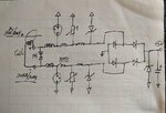
Now I design a CT loop protection circuit.
The CT loop acquires power from 110KV/50Hz to drive a wireless sensor,.
the CT loop will bound to the high voltage wire (normally 500A) directly in the top of a tower.
I wonder if it can protect the following wireless circuit from lighting etc, and how to select the components?
Such as after the 1st gas tube(20kA/10uS), I would place a PPTC, how to determine its spec?
Could you comment it?
Best,
Tony Liu
 

Attachments

  • CT_Loop.JPG
    CT_Loop.JPG
    76.2 KB · Views: 79

And is it possible to simplify the circuit, but without degrade the spec? due to the small space
 

Hi,

Usually CTs need a burden resistance .... to work properly. I miss it in your circuit.
I've heard that CTs without burden can generate overvoltage that even destroy themselves.
Don't design over-protection but forget the esseential.

Now to your protection circuit:
What huge overvoltage with huge engery do you expect?
Since you use protection against your system GND (and not between the CT lines) it seems you don't want to protect against CT generated voltage but externally introduced voltage..
Where does it come from?
If via long cabling, then maybe a shielded cable can be useful..
Why only inductance, but no resistors. Inductances may cause huge ringing, because they can build high Q resonance.
Resistors will reduce Q and thus reduce ringing.
Also resistors simplify voltage and current calculations, because it if frequency independent.

Klaus

Added:
We need to see the complete circuit ... at least as sketch. With HV and the wireless circuit.
(I wonder why you care about HV at all ... since your circuit is wireless)

"Without degrading spec" is a useless requirement .. as long as you don't provide any spec.
 
Last edited:

    tony_lth

    Points: 2
    Helpful Answer Positive Rating
Hi, Klaus,
I know your refer resistor as the following design, but truly the resistor can be ignored due to the zener.
I placed a TVS between the coil +/- to protect CT. Do you have better solution?
There is no cable in the design, just a sensor bonding on the top of the tower.
The whole system sketch is as the following picture.
So I am wonder if the protection is enough for bonding on the 110KV wire and avoiding the lighting etc.?
many thanks.
Best,
Tony liu
 

Attachments

  • SCH_01.JPG
    SCH_01.JPG
    48.5 KB · Views: 65
  • SCH_02.JPG
    SCH_02.JPG
    43.1 KB · Views: 68

Hi,

Still no burden resistor. Most probably you need it for the CT to work properly. Read the CT's datasheet.
Still no power absorbin resustors in error case.

Still I'm unsure what error case you expect.

Generally there is no problem even if your wireless system is connected to the live 110kV wire.
--> no current flow, now power, no problem.

And in case of accidental earth connection: Sell a new one.

Klaus
 

    tony_lth

    Points: 2
    Helpful Answer Positive Rating
Still no burden resistor.
As far as I understand, the OP doesn't want to use the CT for measurement purposes but as power supply. Hence no burden.
 

    tony_lth

    Points: 2
    Helpful Answer Positive Rating
Hi, Klaus,
As FvM say, the design is for micropower acquire system, the acquire current is less than 1mA, if connect a burden resistor, which will waste the most power. So there should be no burden resistor.
Later I contact the CT vendor to check if they embed the burden resistor in CT.
Best,
Tony Liu
 

Hi, Gurus,
The CT vendor confirmed that no any resistor in the CT ring, so could I not place a burden resistor in the circuit?
It will waste most of power in low current, less than 1mA in my circuit, with 5A in the wire.
In case 500A in the wire, I plan to add a shunt regulator and a voltage zener to cope the big power.
Any comment?
Best,
Tony Liu
 

Did you check if the CT has sufficient \[ \int Vdt \] to generate 5V output?
 

Hi, Klaus,
You are right. The CT ring vendor said there should be a burden resistor to determine the voltage, though this would waste some power.
So, when wire current is 5A, CT ring can generate 3mA current, say 0.2mA for burden resistor, so burden resistor should be 5V/0.2mA=25KR.
If 1mA for burden, then its value should be 5KR. I will try this value in the real circuit.
But when wire current is 500A, CT ring can generate 300mA current, because shunt regulator and zener can absorb most of the power,
then
1st question: how to determine the burden resistor power rating? 5W, or 10W?
2nd question: since 300mA*5KR=1500V, so rectifier diode should handle at least 1500V, right?
3rd question: coil +/- will place a gas tube to protect the circuit, how to determine its voltage? I know it should be 20kA/10us, does any voltage should be cared?
@FvM, the CT ring vendor said it can reach 5V, I plan to use diode+C rectifier to raise voltage,
Any comment is welcome, many thanks.
Best,
Tony Liu
 

Hi, Gurus,
I tried the burden resisitor, and finally found 100K can work, other value resistors impacted energy acquire.
So the CT vendor commented to remove the burden resisitor.
Do you have any comment?
Best,
Tony Liu
 

Status
Not open for further replies.

Similar threads

Part and Inventory Search

Welcome to EDABoard.com

Sponsor

Back
Top