Continue to Site

Welcome to EDAboard.com

Welcome to our site! EDAboard.com is an international Electronics Discussion Forum focused on EDA software, circuits, schematics, books, theory, papers, asic, pld, 8051, DSP, Network, RF, Analog Design, PCB, Service Manuals... and a whole lot more! To participate you need to register. Registration is free. Click here to register now.

Do these numbers tell what the input/output is?

Status
Not open for further replies.

scott45

Newbie level 6
Joined
Nov 12, 2011
Messages
14
Helped
0
Reputation
0
Reaction score
0
Trophy points
1,281
Activity points
1,409
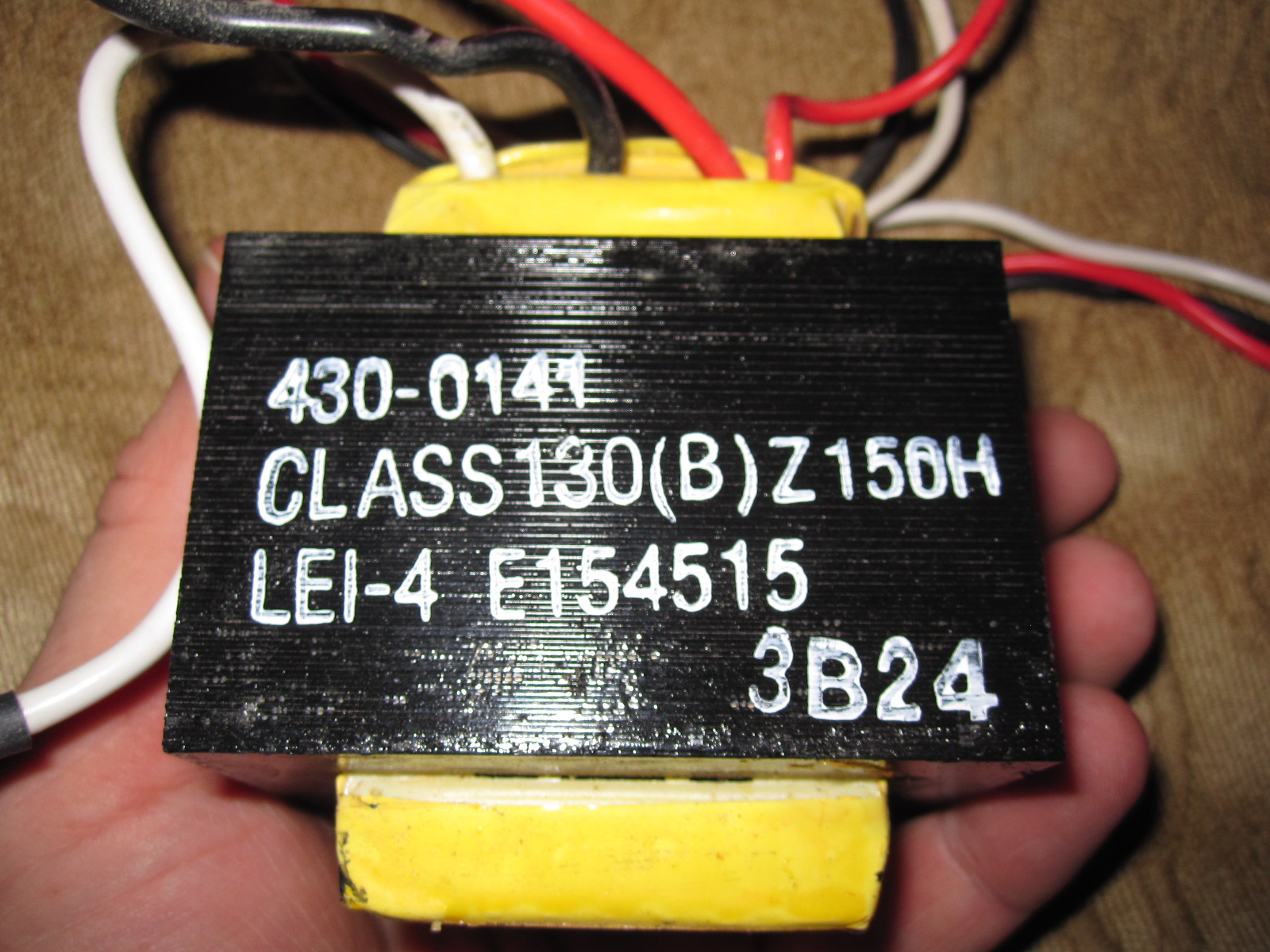
Can anyone with more knowledge than myself tell me, based on the numbers printed on this transformer, what the specs are? I'm looking for something with a 24VDC, 2A output for use as project power supply but I'm thinking this is way bigger than that. The numbers printed here are the only ones on the unit. Thoughts anyone?


Thanks!
 

Hi, Scott. A transformer has at least two windings, a PRIMARY ( input) and a SECONDARY ( output ).
The primary winding measures ( resistance ) much more than the secondary ( usually less than 5 ohms. )
The primarly leads ( wires ) are less guage ( thinner ) than the secondary because the conduct less current ( the primary ).
Identify the windings, apply 110v AC to the primary, then mesaure the output AC voltage.
If you have any doubts just ask again; thats WHAT a forum is for.

---------- Post added at 22:38 ---------- Previous post was at 22:29 ----------

Sorry Scott, just got a closer look at your transformer. The THICK white, black and red wires are surely output.
If you measure resistance they are almos SHORTED. you have THREE wires because it could be CENTER TAPPED.
How many wires does your transformer have?
 

6 wires total. I've got three heavier gauge wires with identical connectors - red, white and black. There are also three smaller wires (also red, white and black) that go into a single 3-pin connector.

Alah - I thought the small the gauge the heavier the wire?
 

OK Scott. Your not THAT badlucky ( As I am! ) Mesaure continuity of the three small gauge wires.
You should find a midpoint which reads equally to the other two wires.
Suppose between red and white you measure 4 Ohms and between red and black you measure 8 Ohms
then the white is CENTER. You should read 4 Ohms between white and the other two wires.
That means that you can apply 110 at the center wire any ANY of the extremes OR 220AC at the exremes.
The same applies to the output. Lets say you measure 24v at two of the out puts and 48 at the other two wires
that means you have 48v center tapped. If you want 24v connect the center with one extreme, if you want 48v connect both extremes.
If you want more output current at 24v connect the center wire and BOTH extremes Shorted.
This doubles the output current capacity, although the foto says its a high current ( POWER ) transformer.

---------- Post added at 23:01 ---------- Previous post was at 22:59 ----------

The smaller the NUMBER of the guage, the THICKER of the wire, which means it can conduct MORE current.

---------- Post added at 23:59 ---------- Previous post was at 23:01 ----------

Sorry AGAIN Scott, correct my last post. Its NOT wrong but it COULD confuse You,
Change 4 Ohms to 400 Ohms and 8 Ohms t0 800 Ohms. It could measure MORE!
The output could read 4 and 8 Ohms.
Do You have a multimeter? Be CAREFULL.
 

The thick wires appear to be secondary and are expected to show very low resistance.
Shorting (combining / joining) any two secondary outputs is not advisable.
The remaining three wires are primary. Can be used for 110 or 220 V application as described above.
Such transformer are suitable to be used as full wave rectifier using two diodes. The centre tap can be used as common.
 
  • Like
Reactions: azad5

    azad5

    Points: 2
    Helpful Answer Positive Rating
Thanks for the input, but before I do anything with the transformer itself I'd like to know if the numbers printed on it mean anything. Based on the size and weight of this thing and the third input/output wire I'm guessing this isn't a good candidate for a power supply built by a noob. :)
 

Hi Scott, Do Uou have an Ohneter OR a multimeter?
Do You know how t measure resistance?
If YES, take the following measures:
1) between red and white
2) between red and black
3) between white and black

record and respond; those will help

Due to the foto you have a POWER transformer, which SHOULD supply your needs.
 

I have a multimeter and know how to measure resistance... that's something at least. Since I'm not sure which red and black wires you're talking about (I've got two of each) I just measured as listed below with my meter's dial set to 200:

1) Fat red to fat white - .3
2) Fat red to fat black - .3
3) Fat white to fat black - .3

4) Skinny red to skinny white - nothing
5) Skinny red to skinny black - nothing
6) Skinny white to skinny black - 3.5

Does that tell you anything useful?
 

LEI stands for Leader Electronics Inc. This is a Taiwan transformers manufacturing company. Having their manufacturing plants in America too. This a pulled transformer from an APC UPS.
Class 130 means the wire insulation withstanding capability of 130° Celsius.
Can you confirm the continuity between White, Red and Black (thick) wires. To me they seem the Black as common and the White and Red as output winding to the output modules. You can check just feeding 12 volts AC to White and Black (thick) wires and check voltage on the other side (the thin wires). May give you an idea for the voltage of the windings. I can not see the colours of the thin wires, may have had an idea for the voltage from the APC UPS transformers.
 

Obviously the fat wires are the secondary.
If the transformer is new? then it ISa POWER transformer and the FAT red wire is not connected
The black and white should be the primary although I would have expected it to measure 10+ ohms.
Plug it to 120v and measure the voltage at the output:
between red and white,red and black and white and black.
 

Raza - I get tone when I check for continuity across all three thicker wires, meaning I can touch any two of the fat wires and get tone. When I test for continuity between any of the three fat wires and the thinner ones I only get tone when I test between any fat wire and the thin red wire.

Alah - I don't mind plugging this thing in and standing back but to be sure, should I be plugging in the fat white/black wires only and ignoring the fat red one?
 

scott,
These wires are Primary when connected inside the UPS. Just connect any 12 volts AC to Black (thick) and White (thick) wires and check the voltage on other side (thin wires) which give continuity (most probably white and black on thin ones). Should be either 110~120 volts or 220~230 volts.
 

The FAT wires should be OUTPUT
Connect the thin wires, which measured 3.5 ohms ( the white and black ) to 120 v.
If the transformer vibrates disconnect it. If not measure the output voltages:
Between the FAT wires:
white and red
white and black
black and red
then check the voltage between the THIN red wire and ALL three FAT wires.
While doing this touch the metal core to check if its heating and HOW MUCH.
If it gets hot disconnect. Please reply.

---------- Post added at 12:32 ---------- Previous post was at 12:21 ----------

Scott do you have a 12 AC source? ANY 12v transformer would work.
IF yes DO as Raza says first.
 

I'm not sure I have a power supply that puts out 12v AC. 12v DC is no problem but 12v AC isn't something I have laying around I'm pretty sure.

Alah - you say any 12v transformer will work... can you please expand on that in case I have what I need and don't know it?
 

scott,
Not essentially needed a 12 volts transformer. You can use even if 6 volts available. You can evaluate the output voltage with same ratio just take the input as reference. Only AC low voltage source is needed. If you have even a 12 volts olf transformer from any adapter will do even. If you find any around you just tell here.
 

Guys - I don't have a power source that puts out AC power except for my wall plugs and I'm not comfortable with hooking this thing up to my home power just yet.

I totally appreciate all the help with this question but it doesn't sound like this is the transformer to use for a first timer's power supply. I think I'm just going to shelve it for now.
 

Hi Scott; Did you receive my schematic?
Do You have a DC Power supply, fixed or variable. If so, it has a transformer which is an AC power supply.
But dont go opening it yet, just try to get ANY 6 or 12 v TRANSFORMER and when you do, come back.

Hi, Raza. I really think its a step up transformer for an inverter; even so, it could work as a step down reversing the input and output wires.
The only doubt I have is that the primary, IN THIS CASE, measures only 3.5 ohm. Whats your opinion?

Scott, measure again and confirm the two wires you said measured 3.5 ohms.
 

Yes it is a pulled out transformer from an APC UPS. I could not confirm the higher side whether it is of 220 volts or 110 volts. That is why I am not asking to connect mains to it but it is confirmed that the lower side is of 12 volts and I am asking to connect a 12 volts AC source so the higher side can be confirmed for proper voltage i,e; 100 volts or 220 volts.
If you connect mains 220, on higher side winding and the the winding is of 110 volts may harm the transformer but if the winding is for 220 volts and the input is 110 volts it will be safe. To me this is the safe way of finding the correct windings.
 

Status
Not open for further replies.

Part and Inventory Search

Welcome to EDABoard.com

Sponsor

Back
Top