mtwieg
Advanced Member level 6
Recently I decided I wanted to make my own stereo FM transmitter without relying on monolithic ICs such as BH1417, SI471X, etc (just to keep it interesting). I plan on using a PLL with a very low closed loop BW (<20Hz) in order to lock the channel center frequency precisely, and injecting the stereo modulated audio into the VCO tuning node. So far I'm looking at using the ADF4360-8 as my PLL/VCO. Is this a reasonable approach? I presume that my distortion will be dominated by the linearity of my VCO, but isn't this always the case?
Also in general, how close does my center frequency have to be to the standard station frequencies (100.0MHz, 100.2MHz, etc)? Is 10ppm enough? And how accurate does my pilot frequency have to be? Also what sort of relative signal strength should the pilot have? And how should I do the 38KHz mixing of the stereo signals?
Thanks in advance.
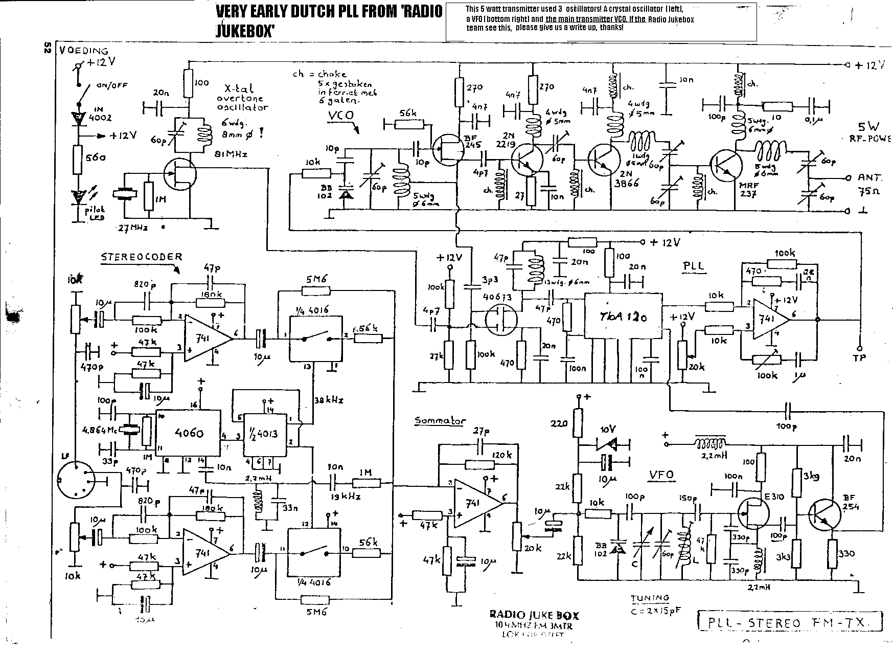
") I then attempted to extend it to being a stereo transmitter as cheaply as possible. The second schematic of the above post shows the result.. I derived the 19/38 kHz tone/mixer oscillator frequencies from the PIC's clock and used a JFET as a linear resistive 'mixer'. While the resulting stereo separation could be improved, it certainly works OK and might provide some inspiration.
I then attempted to extend it to being a stereo transmitter as cheaply as possible. The second schematic of the above post shows the result.. I derived the 19/38 kHz tone/mixer oscillator frequencies from the PIC's clock and used a JFET as a linear resistive 'mixer'. While the resulting stereo separation could be improved, it certainly works OK and might provide some inspiration.