Continue to Site

Welcome to EDAboard.com

Welcome to our site! EDAboard.com is an international Electronics Discussion Forum focused on EDA software, circuits, schematics, books, theory, papers, asic, pld, 8051, DSP, Network, RF, Analog Design, PCB, Service Manuals... and a whole lot more! To participate you need to register. Registration is free. Click here to register now.

DIY high frequency Vpp meter

Status
Not open for further replies.

truffaldino

Junior Member level 3
Joined
Feb 14, 2016
Messages
28
Helped
0
Reputation
0
Reaction score
0
Trophy points
1
Activity points
295
Hello

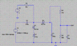
I would like to measure Voltage swing Vpp (or even Vmin and Vmax) in up to 50Mhz range with help od DC multimeter and a reasonably simple and cheap diy circuit.

There is a lot of schematics on the net based on diode rectifiers, but these will not work at high frequency.

I will be grateful for useful links

Truffaldino
 

Something like this was discussed in this thread:
https://www.edaboard.com/threads/349210/

Thanks E-design,

I have checked the schematics you proposed in that thread with the help of two different simulators. They show different results and both do not coincide with ones shown in the thread.

Is was trying to check the circuit for 16Mhz. Is it designed for different range of frequency?
 

Which simulators are you using? Post your results.
 

Which simulators are you using? Post your results.

Hello E-design,

I am attaching results from ltspice, proteus and image from your post

Truffaldino
 

Attachments

  • Proteus.gif
    Proteus.gif
    180.3 KB · Views: 102
  • Schematics ltspice.gif
    Schematics ltspice.gif
    45.4 KB · Views: 101
  • Result ltspice.gif
    Result ltspice.gif
    4.8 KB · Views: 102
  • det.png
    det.png
    33.3 KB · Views: 108

If you are using it at a much lower frequency than 50 MHz, you will need to make the inductor and capacitor/s proportionally larger in value. The inductor must have a high impedance at the test frequency. It also appears you are using the wrong circuit. The member copied it wrong, and I was showing comparison between the two results.
 
Last edited:

I have checked the schematics you proposed in that thread with the help of two different simulators. They show different results and both do not coincide with ones shown in the thread.
I guess, the major difference between simulators is with the BAT54 model parameters. If you use the same SPICE model in all simulations, you get most likely better matching results. There are also (minor) differences in simulation setup.

BAT54 is high current RF diode and not preferred for a high frequency rectifier with relative high impedance level. You better go for a dedicated detector diode. It also seems to me that the complex circuit with diode biasing is involving unwanted side effects.

The intended operation of your detector should be better specified.
 

It doesn't help that he is simulating the wrong circuit.
 

Diode detectors are old hat, work from DC to 30 GHZ depending on diode. I have never seen the inductor in series with one diode, so I Googled "diode detectors" and looked at the images and gave up at over 50 without the inductor. So what is it meant to do?
Frank
 

If you are using it at a much lower frequency than 50 MHz, you will need to make the inductor and capacitor/s proportionally larger in value. The inductor must have a high impedance at the test frequency. It also appears you are using the wrong circuit. The member copied it wrong, and I was showing comparison between the two results.

Thanks E-design,

Indeed I had to read that thread more carefully.

Now I have corrected the circuit as well as inductor/ capacitor values, so that their reactances remain the same while frequency is approximately is 1/3 of 50MHz (i.e. 16Mhz).

Simulation results look nice (see images attached), although there still about 10-20% difference between ltspice and proteus. This is inded due to different diode modelling as FvM noticed above.

Could you please explain principles of operation of this circuit (why do we need inductor etc)?

Also, what is the input impedance of this circuit. Say, for instance, I would like to measure Vpp on 10uH inductor, will the current acrooss this inductor affected significantly by the measurement.
 

Attachments

  • Schematics.gif
    Schematics.gif
    39.8 KB · Views: 102
  • Result.gif
    Result.gif
    7.1 KB · Views: 97

The clue to the need for the inductor is mentioned in the post by FvM.
It is not something new and can be traced back to an old edition of Electronics/1977 and to a more recent mention here **broken link removed** under "Improved Diode Detector"
 
Status
Not open for further replies.

Similar threads

Part and Inventory Search

Welcome to EDABoard.com

Sponsor

Back
Top