Vermes
Advanced Member level 4
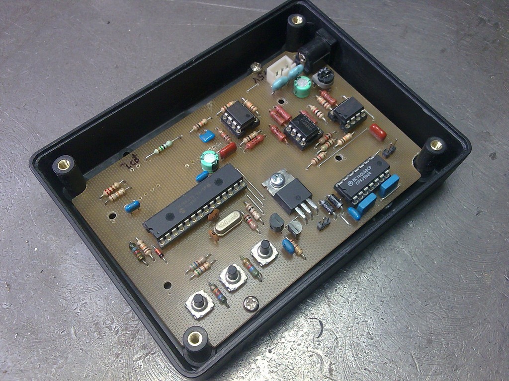
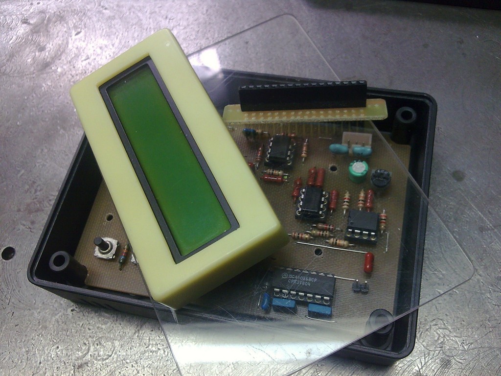
It is a capacitor ESR meter based on PCB and processor's load from:LINK.
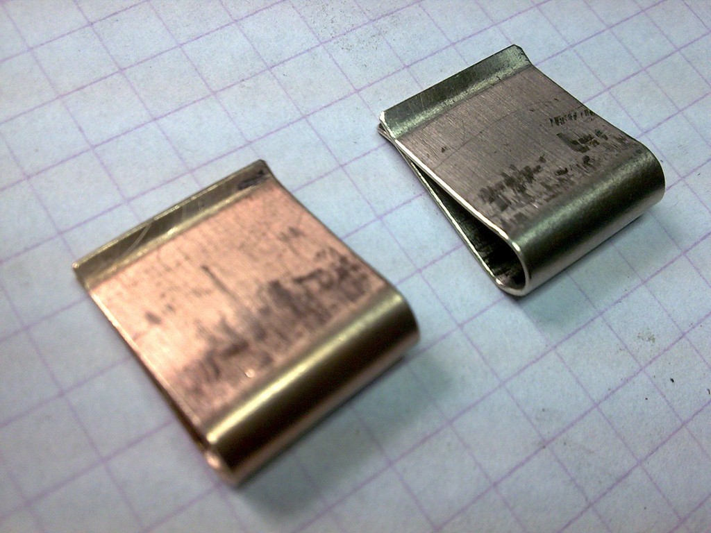
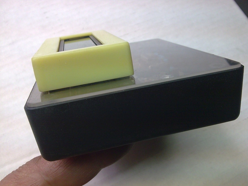
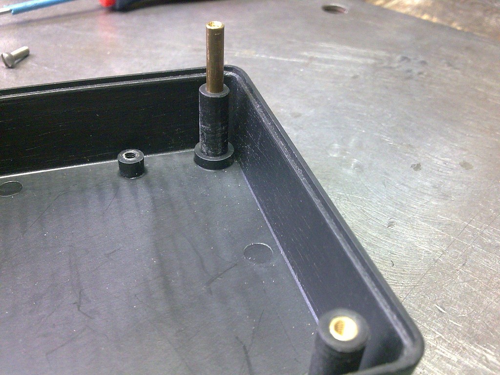
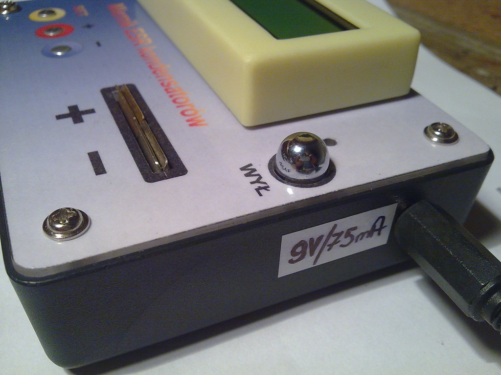
Housing was modified. Threaded sleeves were placed into holes for connecting the halves of the housing. You can also resign from the upper part and so decrease the thickness of the meter. A cover made of a piece of plexiglass was adapted and put in the device. Required holes and two elastic couplings were added. At the end, the PCB needs to be processed and adapted to the inside.
Pictures:


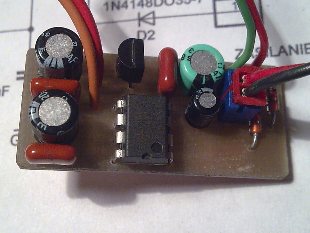
The voltage converter -5V and +5V was screwed to the bottom part of the housing. It was made on a piece of laminate without etching paths, using milling.
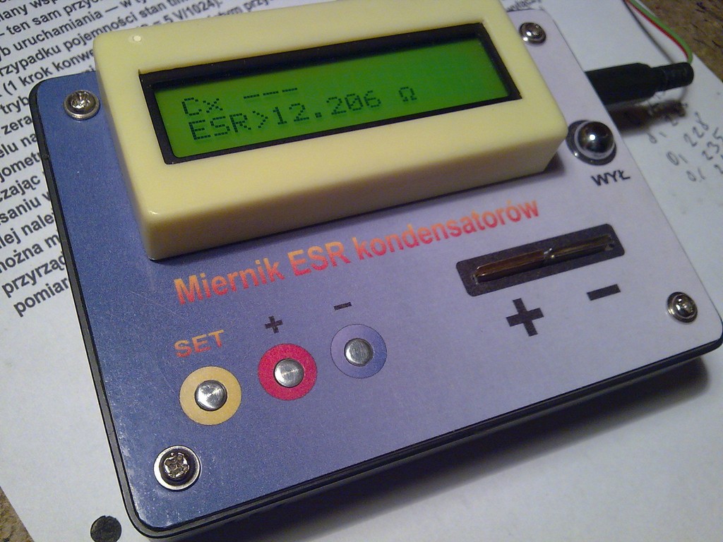
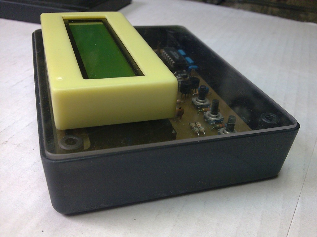
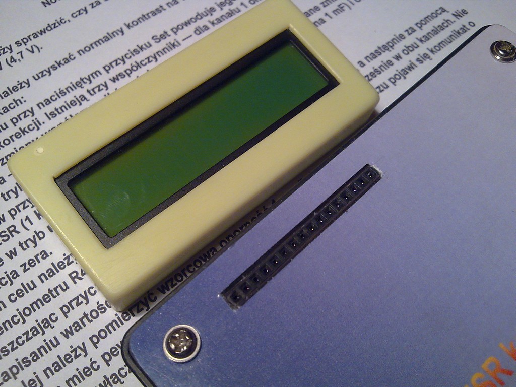
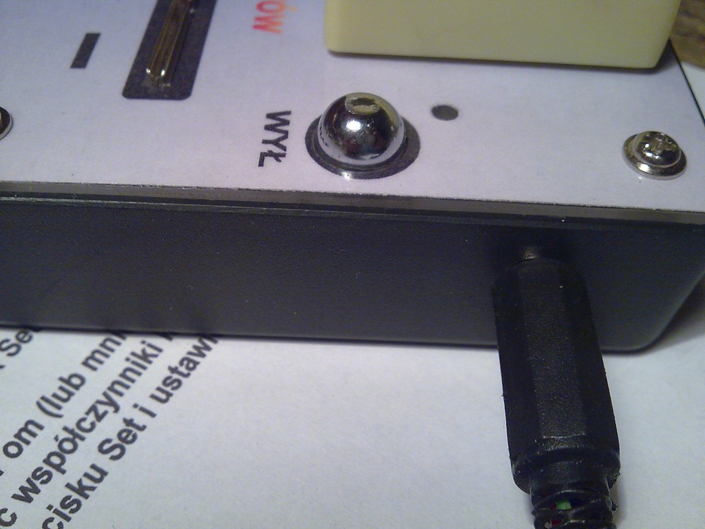
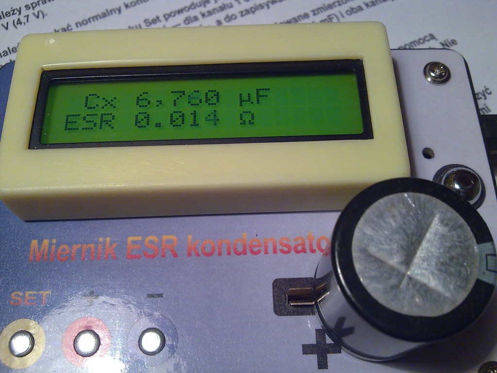
Display was used as a universal module for constructions in place of using 2x16 LCD display. There is no battery supply (because of the lack of place in the housing), but there is an external power supply. There is also a sticker made of self-adhesive paper with descriptions, with a layer of foil on it. Calibration can be made accordingly to the descriptions available on the Internet.
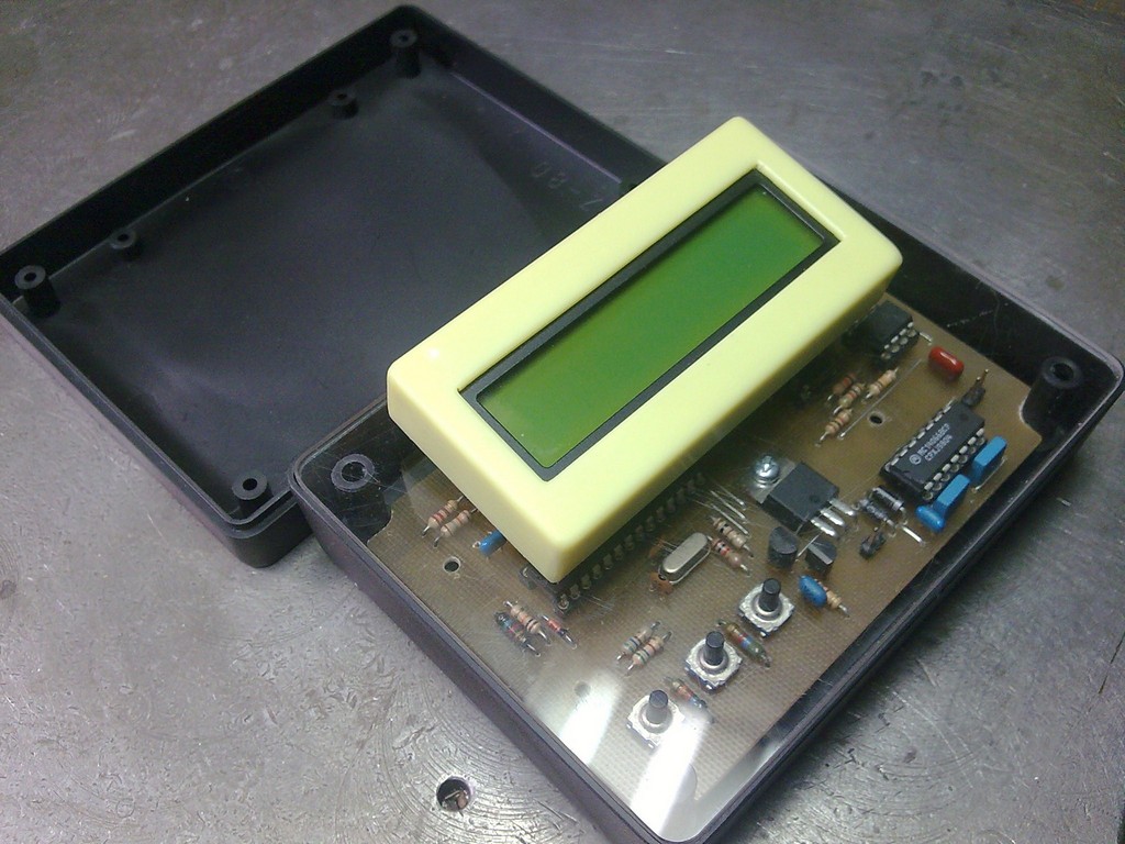


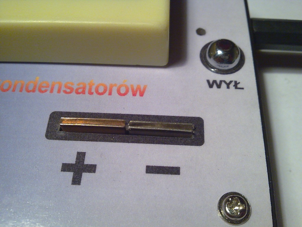
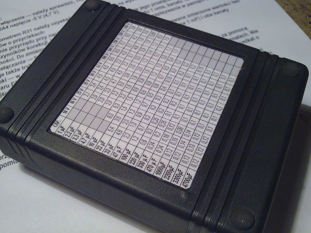
There is information about ESR values for the given capacity on the bottom.
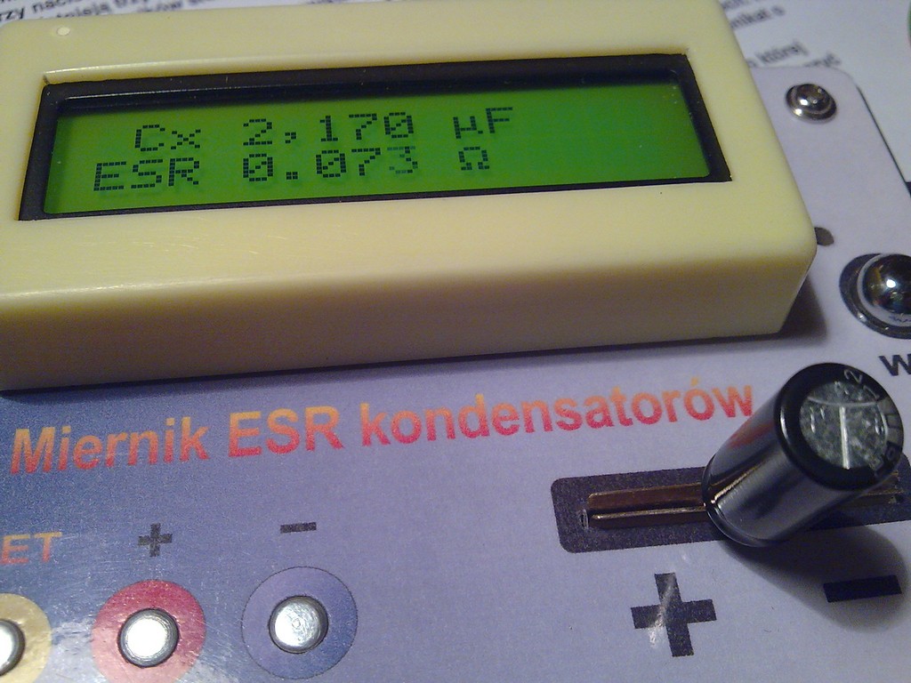
Measurements:
Link to original thread - Miernik ESR kondensatorów