Continue to Site

Welcome to EDAboard.com

Welcome to our site! EDAboard.com is an international Electronics Discussion Forum focused on EDA software, circuits, schematics, books, theory, papers, asic, pld, 8051, DSP, Network, RF, Analog Design, PCB, Service Manuals... and a whole lot more! To participate you need to register. Registration is free. Click here to register now.

Dist. Problems with Amp (AD8065)

Status
Not open for further replies.

janfred

Junior Member level 1
Joined
Jan 7, 2014
Messages
16
Helped
0
Reputation
0
Reaction score
0
Trophy points
1
Activity points
126
Hi guys...

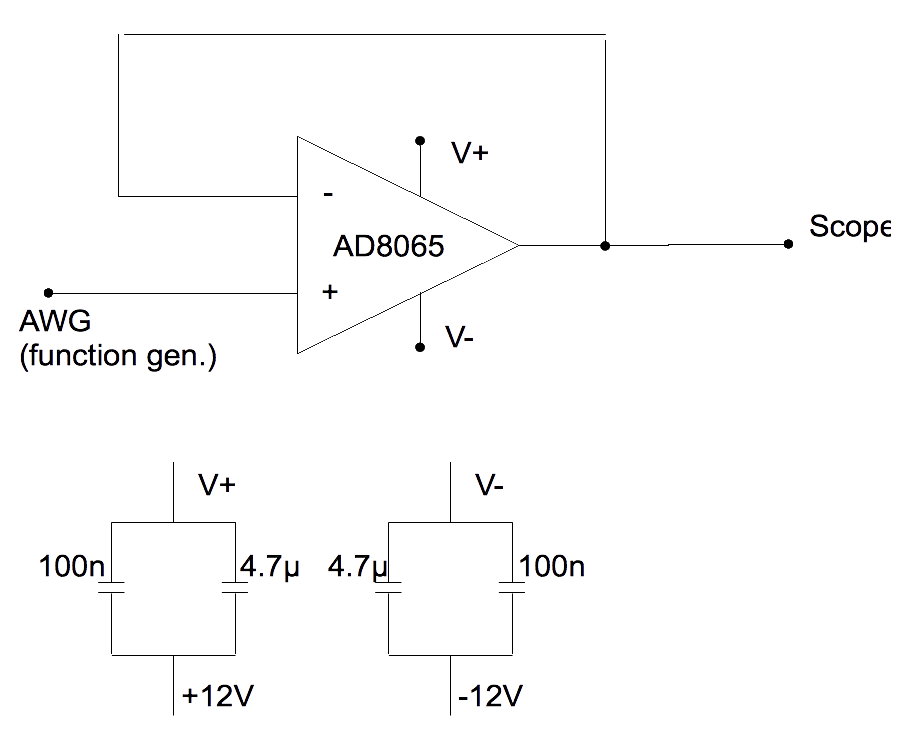
I tried to build up an impedance converter with the AD8065 on a breadboard.
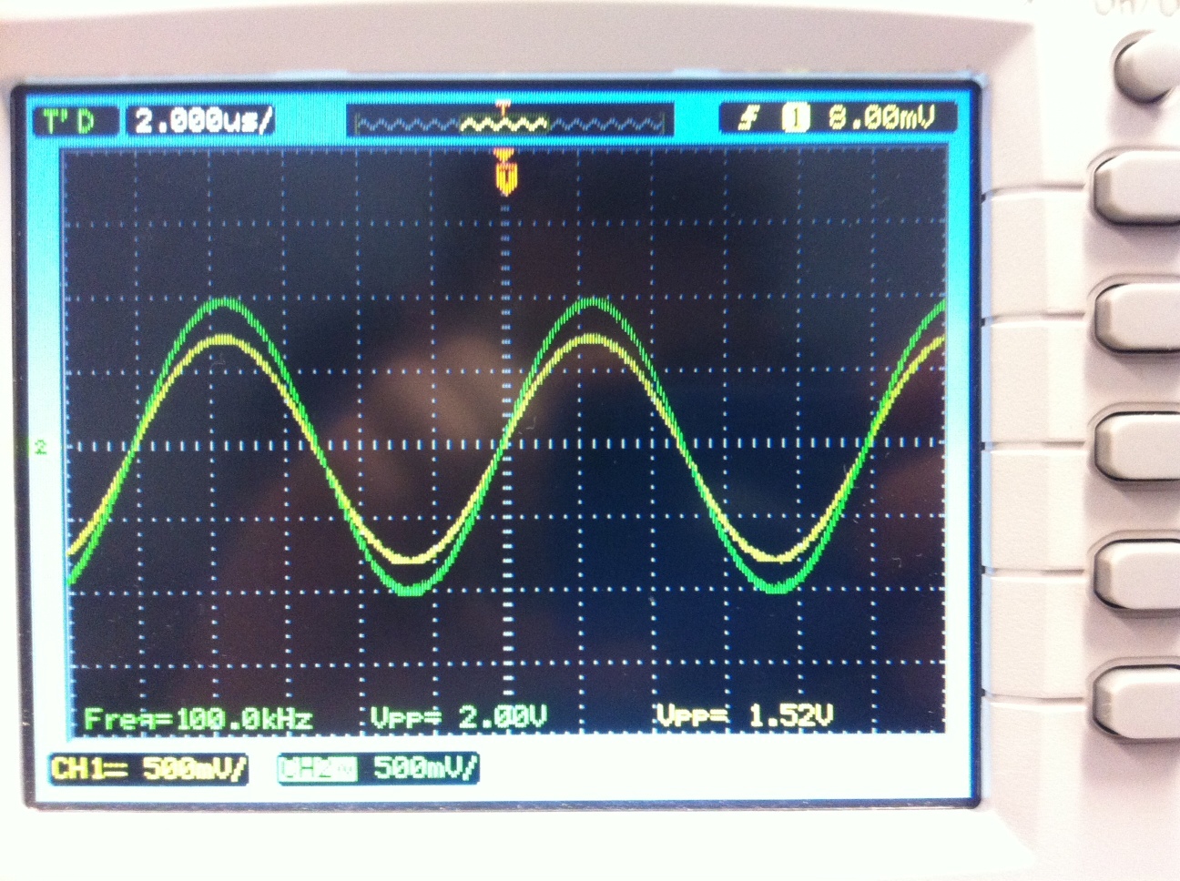
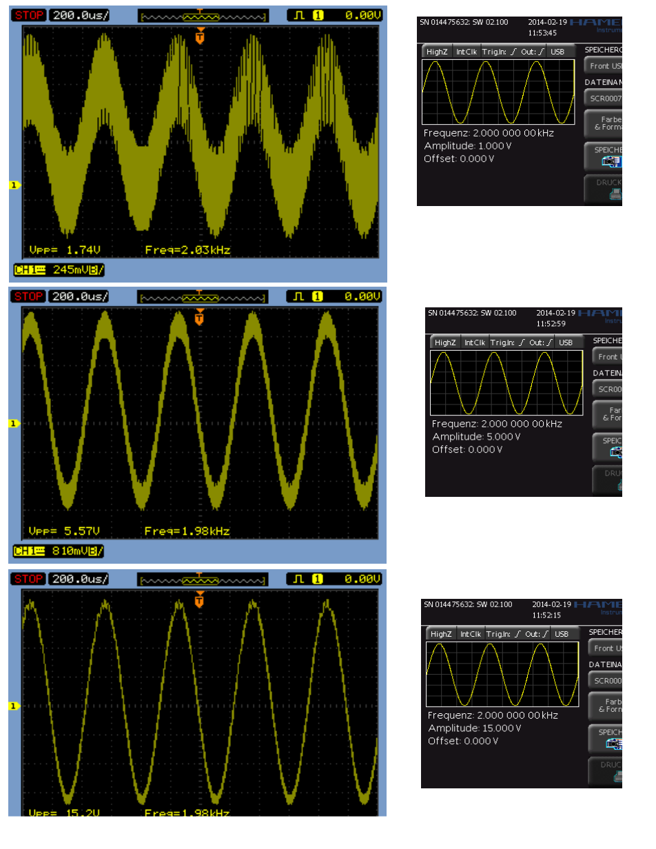
After seeing that there are a lot of problems due to distortion and noise I made some screens with the scope..
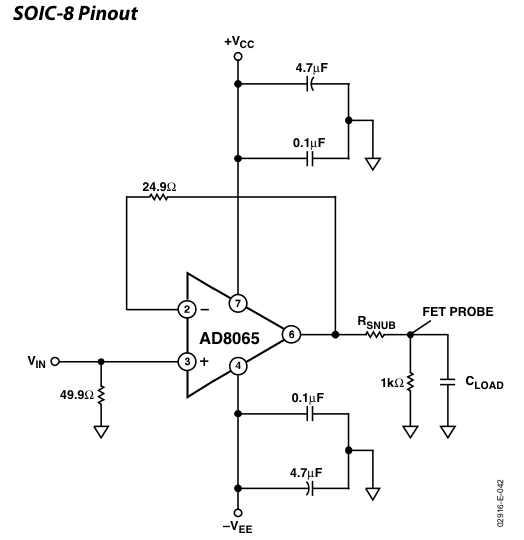
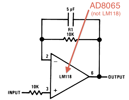
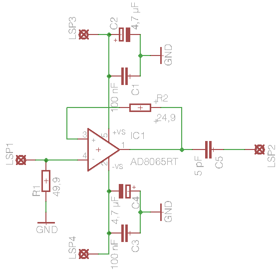
Here is the last circuit I built and the screens from the scope/ the waveform generator.


Would be nice if someone can help me.

regards
janfred
 

The way the schematic is drawn will not work. The +/-12V supplies should attach directly to the op amp +V and -V pins. The capacitors should go from the supplies to ground. Also, be sure the 4.7uF capacitors are installed with the right polarity if they are the electrolytic type.

Edit: Also, "ground" means the common connection of the +/-12V supplies together. This is not shown on the schematic.
 
Last edited:

Well... sorry that I didnt show that in the schematics... That was my fault! Of course the connection of +/- 12 VDC is connected and also the connection to ground.
I made the schematics very fast and so I forgot to draw that.

So lets assume that the connection of Source and the clearing of the source-voltages is right.

OK. Good. Now, how are the grounds on the signal source and o'scope connected? There should be short connections to the circuit ground. Then, check for short connections to the circuit input and output. Make sure there are no long wires forming a "loop" antenna. You may be getting some sort of high frequency pickup because of I/O connections or circuit construction.
 

A very high frequency circuit like that is GUARANTEED to oscillate like yours does when it is made on a breadboard. Use a compact proper pcb instead.
 
The Ground from the scope and the signal source are the same... but actually as you said.. there are connection in form of wire which has a length of 10-15 cm (average)..
So after reading your replies I think that I'm really getting these sort of loop antenna.
Do you think it's possible to reduce the distortion with short wire? And what would be a sufficient maximum length of the (wire) cables I should use then?

I also have some LM318-N here.. with ±5VDC to ±20VDS supply voltage and a small signal bandwidth of 15 MHz which is not that huge as the AD8065 has. And in the datasheet you can also see an example of a fast voltage follower..
https://www.ti.com/lit/ds/symlink/lm118-n.pdf
maybe I should also try this one on the breadboard??

Before I make a pcb.. I just want to be sure that my circuit will work because I can not make the pcb on my own (will have to assign a company with that).

But that were great information!!
Thanks :)
 
Last edited:

There shouldn't be any "wires".

You can make a test circuit as a well considered strip board layout, or soldered on a "baking sheet". My personal favourit is a RF stripboard with a continuous ground plane on the top side.

In any case, the ceramic bypass capacitors must be soldered with very short leads (a few mm maximum) to the OP supply pins and circuit ground.
 
I have made many audio, video and high speed logic circuits on stripboard without any "wires all over the place" (as on a breadboard) and they all worked perfectly and looked good enough to be sold as the final circuit.
 
so thats why you became so rich and that guru at the end Audioguru :p
Little joke you know...

but alright.
I will try to built two circuits.


The first will be the circuit from the AD datasheet with G=+1 and in this case it's an impedance follower right?

The second will be the impedance follower as shown in the LM318 datasheet plus the capacitors for the voltage source to ground.


is it a good idea to try these two layouts?

PS:
I tried the LM318 today on a stripboard and I saw a nice sine output of 10V peak-to-peak voltage as generated with my signal generator for 100 kHz - 1 MHz. From 1 MHz on, the signal starts to distort (expected that though). So as you said.. it works pretty well for me with stripboard and I said 'goodbye antenna i had before' :cool:
 

is there anybody who can help me?
 

the present question was... if it's a good idea to try these two layouts?? but I already did..
the first circuit was great but I had to add a 5pF capacitor in serie to the output (if not so there will be a dc-offset).


Like so, I have a good result but also a drift from the generated sine-wave of 1MHz by 4V Amp.


is it possible to compensate that?????
and there is also a little phase shift... not very big but let me know if I can compensate that too...


I also want to say thanks for your help!
 

Your new schematic has the inputs connected backwards. The input should be the (+) pin 3 and the negative feedback from R2 should connect to the (-) pin 4 pin.
The extremely low value output capacitor forms a highpass filter with the load which causes a phase shift.
The output DC-offset voltage is tiny (1.5mV max) so why worry about it?
Your scope photo does not say which trace is input (green?) and what trace is output (yellow?). At only 100kHz then the output should have the same level as the input but maybe your tiny output capacitor reduces the output.
 

dammit! sorry but I am really upset about myself for being so distracted with the schematic.
makes sense with the highpass filter..
I worry cause I want to use that setup for measurement..
the input is green - output is yellow.
I will change my circuit and correct the mistake with the (+) and (-) pins. I will also omit the capacitor and make some new scope-prints.
thanks for the reply :)
 

Status
Not open for further replies.

Similar threads

Part and Inventory Search

Welcome to EDABoard.com

Sponsor

Back
Top