Continue to Site

Welcome to EDAboard.com

Welcome to our site! EDAboard.com is an international Electronics Discussion Forum focused on EDA software, circuits, schematics, books, theory, papers, asic, pld, 8051, DSP, Network, RF, Analog Design, PCB, Service Manuals... and a whole lot more! To participate you need to register. Registration is free. Click here to register now.

Discontinuous conduction mode of buckmode converter: weird waveform problem

Status
Not open for further replies.

flightback

Newbie level 3
Joined
Jan 14, 2013
Messages
4
Helped
0
Reputation
0
Reaction score
0
Trophy points
1,281
Activity points
1,316
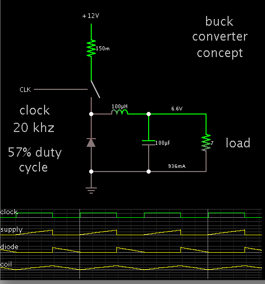
In a buckmode (low-side switch) converter constructed, we encounter a weird problem.

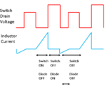
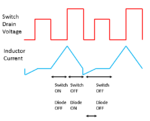
There is a fourth state between diode conduction zone (switch off, diode on) and dead zone (switch off, diode off) as shown in the attached illustration. This significantly harms the converter's efficiency. And we have no clue why this is happening. Any help would be appreciated.
 

Attachments

  • DCM Waveform.PNG
    DCM Waveform.PNG
    13.5 KB · Views: 128
  • DCM Waveform.PNG
    DCM Waveform.PNG
    14.7 KB · Views: 135
Last edited:

To prevent this dead zone , u must be in a continuous mode.
This simply can be achieved by increasing the filter inductance or increasing the switching frequency or both.
 
Coil current should ramp upward until the moment of switch-Off. Then coil current needs to start ramping downward immediately.

From the look of your waveform, it appears your diode is not allowing current through the coil.

Screenshot showing waveforms in a buck converter:


The coil is operating at the border between continuous and discontinuous mode.
 
Yes, I understand there are normally three states, when it operates in DCM:
1. Switch ON, Diode OFF;
2. Switch OFF, Diode ON;
3. Switch OFF, Diode OFF.

However, as shown in the scope image attached, there is a weird period (highlighted in red) in our converter between state 2 and state 3. In this weird period, the switch conducts reverse current...
Did I explain my question clearly?

DCM.png


My converter is buckmode, and the switch is on the low side. If the attached schematics helps you understand the weird waveform...

Buckmode.PNG
 

I think the only thing that can cause such a waveform is some large parasitic inductance in the circuit.
 
Could you elaborate more?

We also suspected something wrong with the inductor. However, it turns out that the frequency response and magnetics saturation current of the inductor are very reasonable for the application...

If it is a large parasitic inductance, between which node and which node should I add an inductor in the schematics to reproduce the problem in simulation first?

I think the only thing that can cause such a waveform is some large parasitic inductance in the circuit.
 

I'm not quite sure... could you tell us more about the specific components, including the voltage ratings on the FET and diode?

I can come up with somewhat similar waveforms in spice by adding inductance in series with the diode, and adding a zener in parallel to the FET to emulate the effect of avalanche breakdown.
 
I believe I see ringing to the right of your tall red rectangle. I don't know for sure if that is causing your problem, but it might help if you could track down its source. Perhaps by changing the capacitor, or reducing the frequency, etc.
 
I chose the FET and diode quite over-rated for the application. Input voltage was 30V. And the FET and Diode have BV above 50V.

Attached is a LTspice simulation. I could not reproduce the weird region between diode conduction zone and the dead zone (where neither diode or FET conducts).

I am aware that in the dead zone, the drain voltage of the switch could ring significantly. However, the weird region is so long in duration and can't be counted as half period of the ringing...
 

Attachments

  • Discontinuous conduction mode.PNG
    Discontinuous conduction mode.PNG
    60 KB · Views: 153
  • Discontinuous conduction mode.asc.zip
    713 bytes · Views: 93

Correct, that's what I observe as well. The ringing shouldn't be the problem, but it looks like something is storing energy in the circuit even after your main inductor has discharged all current.

Since we have no solid idea why that waveform is there, you should try to simultaneously measure current on other paths to see which path the current is taking. It has to go somewhere...
 
In a few simulations, I also saw brief backward flow through the coil at a part of the cycle when there was no way it should be happening.

Then someone recommended that I reduce the time step. This cured the problem.

Hmmm... Now I realize I forgot yours is a real-life circuit. Not a simulation.

Is your power source a battery? I seem to recall seeing inductive action (tendency to ringing) where a battery was present. I'm not sure this can account for backward flow however.
 
Last edited:
Status
Not open for further replies.

Part and Inventory Search

Welcome to EDABoard.com

Sponsor

Back
Top