Warpspeed
Advanced Member level 5
- Joined
- May 23, 2015
- Messages
- 2,366
- Helped
- 773
- Reputation
- 1,548
- Reaction score
- 789
- Trophy points
- 1,393
- Location
- Melbourne, Australia
- Activity points
- 20,317
This whole problem of isolated gate drive could be simplified if your main switching device was a P channel device instead of an N channel device.
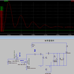
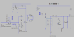
I have on occasion successfully used a high side driver circuit like this, which is a Warpspeed invention:

Fast high current gate drive is via the 100nF coupling capacitor and a "grunty" gate driver chip.
A very weak dc coupling path runs in parallel with that, to ensure the gate is truly dc coupled.
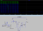
I have on occasion successfully used a high side driver circuit like this, which is a Warpspeed invention:
Fast high current gate drive is via the 100nF coupling capacitor and a "grunty" gate driver chip.
A very weak dc coupling path runs in parallel with that, to ensure the gate is truly dc coupled.