Continue to Site

Welcome to EDAboard.com

Welcome to our site! EDAboard.com is an international Electronics Discussion Forum focused on EDA software, circuits, schematics, books, theory, papers, asic, pld, 8051, DSP, Network, RF, Analog Design, PCB, Service Manuals... and a whole lot more! To participate you need to register. Registration is free. Click here to register now.

[SOLVED] Disarm button Circuit

Status
Not open for further replies.

owais131

Newbie level 5
Joined
Mar 3, 2008
Messages
8
Helped
0
Reputation
0
Reaction score
0
Trophy points
1,281
Location
Karachi, Pakistan
Activity points
1,340
Dear Seniors and Respected Members,

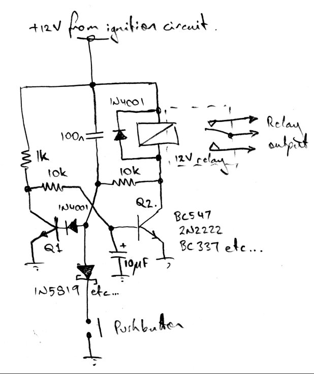
I want your precious time to help me in a simple circuit. I need to make Arm/Disarm Circuit for a vehicle (12V DC). The circuit will work as follows:

1. When vehicles ignition is ON, the Output should be enabled and vehicle is killed.
2. When disarm button is pressed, the output should be released and vehicle is mobilized.
3. When ignition is turned OFF, the output should be enabled again. (this is not required but if this is possible that it is good)

Condition:
The disarm button should take negative (Ground) as input to trigger the circuit, as this button is common to another circuit that needs a ground input too.

I have searched the forum and found some similar circuit , see below:
link https://www.edaboard.com/threads/202518/
71_1297835733.jpg


But it takes positive 12 volts as an input. I need a ground (neg) as input. Thanks in Advance.
 

Heya owais,

I've sketched a simple arrangement using a couple of transistors that will (hopefully :) fit the bill!


It's called a "bistable", meaning the circuit can be in one of two stable states (indefinitely). One of the states corresponds to the relay being off (i.e. engine disabled), and the other turns the relay on (and enables the engine). When the ignition circuit is first switched on, the 10 uF capacitor at the base of transistor Q2 ensures it is held off until Q1 turns on. This prevents the relay from turning on and thus the circuit 'wakes up' with the ignition disabled. Pressing the pushbutton turns Q1 off and allows Q2 (and the relay) to turn on, thereby enabling the engine. Pressing the pushbutton further has no effect, and the engine remains enabled until the ignition is turned off, at which point the cycle begins again.

Let me know if you have any problems with the circuit as drawn - the component values aren't terribly critical - just ensure the relay is a low-current type (for the transistors shown). You could probably use BD139s (or similarly rated medium power transistors) and reduce the 10K base resistors to ~1K if you want to directly switch an automotive type relay.

The 1N5819 Schottky diode (and 1N4001 in series with Q1's base) isn't strictly necessary if the pushbutton is on its own isolated circuit, but I've included them as you mentioned the button was shared with something else and this way the circuit is protected against whatever that other circuit might be!

Just a word of caution when installing your own electronics into a car [and especially when it has the capacity to disable the engine] - the automotive electrical system is a horrible electrical environment! You have to ensure whatever you add is sufficiently protected against transient over- and undervoltages and that electrical 'noise' doesn't cause unintended operation of your circuit. It is for the latter reason in particular that I selected a bistable for your application - electrical noise on the pushbutton signal won't cause the circuit to change state and stop the engine. (My first car 'featured' a homebuilt security system that would annoyingly arm itself whenever I turned on the headlights...) I would strongly recommend AGAINST circuits like the one in your original post - aside from not having any switch 'debouncing', the floating clock input will cause you no end of random triggering trouble (and possible ESD damage to the 4013). Using a 25V (or greater) rated electrolytic type for the 10 uF capacitor should make the circuit suggested fairly indestructible from the perspective of transient overvoltages too.

Good luck :)
 
Last edited:
Thanks thylacine1975 , i have made the circuit and it is continuously keeping the relay in ON State. I have also bypassed the diodes one by one but nothing happened. Any suggestions ?
 

Hmm... no idea! Let's debug and see where it takes us...

Here's the plan:
(And a bit of notation: when I say a transistor is 'ON', I mean base current flowing with the voltage across the base-emitter ~0.6V, and current flowing into the collector. 'OFF' = no collector current, Vbe ~ 0V).

Since the circuit is a bistable, we should be able to flip it between its two states by turning the alternate transistors off. If the relay is ON, then that means Q2 is turned on (which it obviously isn't supposed to be until the button is pushed). All you need to do to turn Q2 off is to short the base and emitter together (in practice this is easily performed with a pair of needle-nosed tweezers or a flat bladed screwdriver) - this will rob the base of drive current, and force the transistor off. This should turn the relay off - if it doesn't, check that Q2 and/or the relay is wired correctly.

Turning Q2 off should immediately turn Q1 on. This will be evidenced by the relay clicking off and STAYING off after you short the base-emitter of Q2. If it clicks back on the instant you remove the short, then either Q1 is dead, wired incorrectly or there's something amiss in the circuitry around the base. Check the 10K resistor and that the 1N4001 is the right way around. The voltage on the base of Q1 should measure ~0.6V while you have the Q2 short in place.

If the relay clicks off as it should, pressing the button should turn it on, since the button simply shorts the base-emitter of Q1 in the same way you just manually did Q2. Shorting Q2 should then start the whole cycle over again...

If this all looks good, then the circuit is simply waking up in the wrong state. The brute-force thing to try would be to increase the 10 uF capacitor to ~ 100uF and perhaps even parallel it with a 10K resistor. I could start guessing about reasons for Q1's delayed turn on (is the 100n capacitor in place?) but I'll hold off hypothesising until I hear how you go :) Let me know how you fare, as well as any observations along the way which might offer clues...

Good luck!
 
Thanks alot thylacine1975 , it the previous circuit is working Gr8, i wonder why it is not working earlier , thanks a lot :)
 

Hi thylacine,

This circuit helped me a lot in my project. Can you please tell me, If I need a timer in it? For instance, I want to disarm this circuit either with the push button or it will automatically disarm but itself after some time(1 minute).

Thanks in advance.
 

Heya toyosiazeez - no there's no timer inherent in the bistable design I posted in post #2. It automatically arms itself on power-on and then sits in that state indefinitely... it can only be disarmed by pressing the pushbutton.
You'd need to add an external delay element to the pushbutton input if you wanted it to disarm itself automatically.

P.S. I'm pleased it proved useful for you! Thanks for letting me know :)
 

Status
Not open for further replies.

Similar threads

Part and Inventory Search

Welcome to EDABoard.com

Sponsor

Back
Top