Continue to Site

Welcome to EDAboard.com

Welcome to our site! EDAboard.com is an international Electronics Discussion Forum focused on EDA software, circuits, schematics, books, theory, papers, asic, pld, 8051, DSP, Network, RF, Analog Design, PCB, Service Manuals... and a whole lot more! To participate you need to register. Registration is free. Click here to register now.

Diode Clipping issue

Status
Not open for further replies.

kingssk

Junior Member level 2
Joined
Jul 7, 2009
Messages
21
Helped
0
Reputation
0
Reaction score
0
Trophy points
1,281
Location
india
Activity points
1,417
Hi,

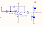
I have designed the waveform clipper Circuit using diode, please find the attachment for my design,

In this my input at P2V-IN is 0-5V square wave and am expecting the output as +6V to -8V square wave output but am getting output as +10.2V to -10.2V could any one please tell me what will be the issue why the clipping is not happening here?

**broken link removed**
 

Attachments

  • Diode Clipper.png
    Diode Clipper.png
    17.4 KB · Views: 74

hi,
Whats the source impedance of the +6v and -8v, how are they generated.??

E
 

Hi,

its generated using L78L06 and MC79L08 regulator from +/-12V supply
 

Your problem indicates Forward voltage is not clipping like both diodes are not in circuit or connected to output.

Please verify voltage on the diodes when output of OA is rail to rail and take appropriate action.

Also note from Voltage Output Swing specs for VS = ±2.25V to ±18V, there is a current limitation on the linear range near the rails.+ rail-to-rail drop voltage with load impedance.

(V+) – 0.6V for RL=600 Ohms ...
(V+) – 0.2V for RL=10k

Also note your +/12V supply and output swing is only +-10.2V which implies excessive load current, but if the diodes are NOT conducting, what is loading it?
 

hi,
Your problem is in using Vregs to bias the clamp diodes.

Look at these two images from an LTSpice sim.

Image #5 shows correct clamping when the diode bias source has a low impedance, it clamps OK.

If you now add say a source impedance of 200R the clamps fails. Image #6.

This is because you are driving the 7806 and 7908 out of conductance by applying a voltage 'higher' than the regulators output, so its output impedance rises and it cannot sink the diode current

E
 

Attachments

  • AAesp05.gif
    AAesp05.gif
    33.5 KB · Views: 57
  • AAesp07.gif
    AAesp07.gif
    34.6 KB · Views: 68
esp1` is correct. If you put your feedback on diode side and insert 10k instead of 100 ohm resistance. you can load the TL regulators with ~1~10k to prevent pullup from this load
 

esp1,

Thanks for your reply,

but in my case i have only Vreg to bias the clamp diode, what can i do to solve this issue with the same Vreg
 

hi,
Use a low cost dual OPA to isolate the Vregs from the diodes, [ which is a common way of doing it] as this image shows, also increase the 100R to 1K in order to reduce the sink current.
E
 

Attachments

  • AAesp08.gif
    AAesp08.gif
    38.9 KB · Views: 61
Status
Not open for further replies.

Similar threads

Part and Inventory Search

Welcome to EDABoard.com

Sponsor

Back
Top