danilorj
Member level 3

- Joined
- Apr 17, 2014
- Messages
- 60
- Helped
- 1
- Reputation
- 2
- Reaction score
- 1
- Trophy points
- 8
- Activity points
- 462
Hi guys,
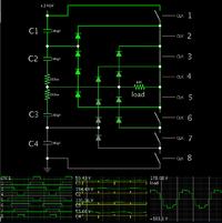
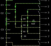
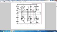
I'm trying to analyse the principle of working of this diode clamped multilevel inverter.
Let's say I want to analyse just the part within the red rectangle in the figure attached.
If all the switches below are on than Va=0, Ok.
Now when Sa1,Sa'5,Sa'4,Sa'3a and Sa'2 are on and Sa'1 is off, Va=Vdc.
This is what I don't understand, I don't understand how these diodes can clampe.
For example, at anode of diode D4 would be Vdc and at the cathode of it what would be?
For it to conduct the cathode voltage should be lower than the anode, how can I assure this?


