Continue to Site

Welcome to EDAboard.com

Welcome to our site! EDAboard.com is an international Electronics Discussion Forum focused on EDA software, circuits, schematics, books, theory, papers, asic, pld, 8051, DSP, Network, RF, Analog Design, PCB, Service Manuals... and a whole lot more! To participate you need to register. Registration is free. Click here to register now.

Digitally Controlled Variable Resistor (for 555 freq control)

Status
Not open for further replies.

external_reset

Newbie level 3
Joined
Aug 19, 2010
Messages
3
Helped
0
Reputation
0
Reaction score
0
Trophy points
1,281
Location
California, USA
Activity points
1,316
I need a circuit for a digitally controlled variable resistor to function as the frequency determining component in an astable 555 circuit. It is required to:

* vary from 2500K to 0K
* in 256 steps
* with a tolerance of +/- 2% or less
* be able to float in-circuit

I looked at the various offerings by Analog Devices and Maxim but I could find values that only went as high as 1000K, tolerances in the range of +/-30% and no ability to float (i.e.digital potentiometers), non of which fit the bill.

I could do it with a Binary Weighted Ladder (as described in Digitally Controlled Variable Resistor), but I would have to calibrate the top end. Does anyone know of a way to do it with a R:2R ladder? Or is there an IC that I don't know about?

Here's the schematic of the existing circuit that I want to modify:
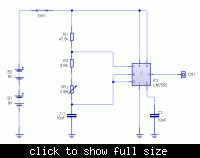
 

Not quite sure why you cannot change your other component values to get the resistance requirement lower. You still might have a problem with the maximum voltage for digital pots when you operate the 555 at 18V.

The datasheet for the LM317 contains a very old design for a digital voltage control. You might consider that same concept for your device, particularly if you only need a few steps.

Here is that circuit:

attachment.php


John
 

Attachments

  • LM317 copy.gif
    LM317 copy.gif
    9.1 KB · Views: 361

If you going to change other components change the LM555 and use digital counter or PLL
 

If you going to change other components change the LM555 and use digital counter or PLL

In this case the application relies on the unique characteristics of the 7555 timer's output--just the right rise/fall time, and impedance. Also, the fact that it can function at the "high" voltage levels involved is a huge determining factor. Not to mention that I'm actually using a 7556 dual timer and doing a cascade sort of thing to distort the waveform with analog mixing between the two, etc. (with even more DCVRs involved), which would be difficult to reproduce any other way.

BUT, I did find the AD5291 Digital Rheostat [DR] that can operate at voltages up to 33V, has 1% over all resistance tolerance with 256 steps. BUT it only comes in three values: 20K, 50K and 100K. I think I can get those to work for all the other DRs involved, so that still leaves the 2M5, which needs to be high, because I need the dynamic frequency range with lack of duty cycle shift.

Does anybody know of a digital rheostat with an R value up in the 1 to 2 Meg range? I think I can adapt the circuit to use a 1 Meg DR.
 

You didn't manage to clarify why you mean to require the variable resistor parameters exactly as said. So we can't determine, if there is any understandable reason for it, or if you are only lacking the power of imagination to achieve the circuit purpose in a different way, using existing parts.

Scaling the circuit to a different impedance level would be a simple modification, but there are also options to use different topologies, controlled current sources rather than resistors and much more solutions from the whole universe of analog circuits.

I'm however quite sure, that you won't find a > 1M digitally controlled resistor on the market.
 

Status
Not open for further replies.

Part and Inventory Search

Welcome to EDABoard.com

Sponsor

Back
Top