Continue to Site

Welcome to EDAboard.com

Welcome to our site! EDAboard.com is an international Electronics Discussion Forum focused on EDA software, circuits, schematics, books, theory, papers, asic, pld, 8051, DSP, Network, RF, Analog Design, PCB, Service Manuals... and a whole lot more! To participate you need to register. Registration is free. Click here to register now.

[SOLVED] digital QAM modulation/generation

Status
Not open for further replies.

ashugtiwari

Full Member level 4
Full Member level 4
Joined
Dec 12, 2008
Messages
218
Helped
45
Reputation
90
Reaction score
44
Trophy points
1,308
Visit site
Activity points
3,310
Hello All,
Ok, i may be asking dumb question but by far my knowledge of communication systems is rudimentary. So, sorry if i make any silly statement.
Im trying to understand 16 - QAM signal. Since, I could not figure out from whatever i found on google. So, according to ideal modulator, dividing a byte into 4 bit values such that odd positioned bits will form Q component and even positioned bits in byte will form I component. Then the 4 bit values will modulate the sine and cosine component and will generate final I and Q component, then the final result is added together and transmitted on channel.

Is this the way QAM is generated or the method is different for digital 16 QAM? Since, when i saw constellation diagram i got confused that, only three voltage levels and 16 values, so the 12 different phase positions will make up for it. But how? Since, every 4 bit value will have its own amplitude value.

In a way, im bit confused. Sorry, for such basic question, but i could not find any satisfactory answer.

Thanks for answers.

Ashutosh
 

Hi Ashutosh

Why do you mention three voltage levels?
In 16QAM you have 4 possible values for I and the same 4 for Q, giving the 16 possible combinations of the constellation.
Regards

Z
 
Hi zorro,
thanks for reply. looking at constellation diagram for 16 QAM, there are only 3 voltage levels and as far as my understanding for QAM, the same diagram applies for both I and Q component, so irrespective of which component, the constellation diagram applies to both components. If im wrong plz correct me, since this is what i understood from all online articles and diagram.
Also, u said there are 4 for I and Q, how are they separate from one another when it comes to modulation while using same constellation diagram for both components? Is it like 8 4-bit codes which are odd decimals are assigned to only Q component and vice versa for I component?

Thanks
Ashutosh
 

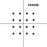
This is the constellation for 16-QAM:

modulation-constellation-16qam.gif

It has 4 levels for I (-3, -1, 1, 3 in the horizontal axis) and the same for Q (in the vertical axis).
If you have something else, please show it.

Z
 
So, this is how voltage levels are assigned i guess. So, do u mean, the voltage at constellation point is arithmetic sum of respective values on Q and I axis?
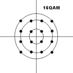
I actually understood this like as displayed in image. Every circle is one analog amplitude, for smaller circle the amplitude is something 0.375V, for middle its 0.72V and for outer circle its 1V as a normalized voltage.modulation-constellation-16qam.gif
The three voltage levels with different phases will contribute to 16-QAM. So, its like for pi/4 and 0.375V, there is one 4 bit code and i can start sine wave from that phase with that amplitude.
But, if i follow the ideal modulator principle of 16-QAM, i.e. apply ASK to sine and cosine carrier wave according to 4 bit code and add I and Q eventually; will i get the same result? or is digital encoding of QAM is different from analog?
 

... So, do u mean, the voltage at constellation point is arithmetic sum of respective values on Q and I axis?
Not the arithmetic sum of respective values on Q and I axis. As you said in your first post, I and Q modulates cos() and sin() carrier respectively and the result is added for transmission. The result is modulated in both amplitude and phase, it's true, but the important thing is the values if I and Q components.
The receiver "measures" in some way the coordinates in I and Q axes for each received symbol and determine which of the 16 point if the constellation is closer. In that way it detects the 4 bits of the symbol.

But, if i follow the ideal modulator principle of 16-QAM, i.e. apply ASK to sine and cosine carrier wave according to 4 bit code and add I and Q eventually; will i get the same result?
Yes.

...or is digital encoding of QAM is different from analog?
Data is digital and it is coded in an analog signal.

Regards

Z
 
*** damn, after 5 hours of brainstorming all ur comments and al the QAM info online, i finally understood, everything u said for QAM. now im thinking how can i miss something so simple.
Thanks mate. It took some time for me to understand, but u really did great help. Thanks again for that :cool: . u rock zorro.
:)
 

Status
Not open for further replies.

Similar threads

Part and Inventory Search

Welcome to EDABoard.com

Sponsor

Back
Top