Continue to Site

Welcome to EDAboard.com

Welcome to our site! EDAboard.com is an international Electronics Discussion Forum focused on EDA software, circuits, schematics, books, theory, papers, asic, pld, 8051, DSP, Network, RF, Analog Design, PCB, Service Manuals... and a whole lot more! To participate you need to register. Registration is free. Click here to register now.

DIGITAL ESR METER WITH IC ICL7107

Status
Not open for further replies.

pgr2002

Member level 5
Joined
Aug 1, 2013
Messages
87
Helped
0
Reputation
0
Reaction score
0
Trophy points
1,286
Location
Hyderabad, India
Activity points
2,015
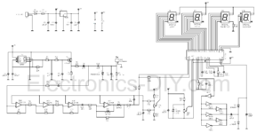
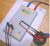
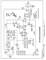
I came across this ESR meter with IC's - ICL7107, 555, 4049, TCL274CN, & other common parts. In the schematic diagram (attached) the four 7 segment displays are mentioned in sequence as LD1 (ones), LD2 (tens), LD3 (hundreds) & LD4 (thousands). In the PCB or in veroboard, etc the sequence should be (as per my knowledge goes) soldered as LD4, LD3, LD2 & LD1. Is this correct or it should be soldered as per the diagram starting from LD1, LD2, LD3 & LD4. Can anyone confirm which one is correct.
 

Attachments

  • Circuit Diagram.png
    Circuit Diagram.png
    781.8 KB · Views: 629
  • ESR meter.png
    ESR meter.png
    310.6 KB · Views: 475

Hi,

A schematic is not neant to show the physical/mechanical placement. It just shows the electrical connections.

The digits are marked (from left to right) "Einer", "Zehner", "Hunderter", "Tausender", which means "1s", "10s", "100s", "1000s".
So I can confirm that the order is reversed than you expect.

Besides this I doubt it can work correctly, but didn't go deep into it. So maybe it works...

One example for doubtful information:
R6 is marked with "47k, 1W". The power supply is 5V, so the max dissipated power is 5V x 5V / 47,000 Ohms = about 0.5mW.
A factor of 2000 away ftom 1W.
The problem I see is that often high power resistors are wire wound and thus may introduce a lot of inductivity. Maybe this hurts the result, maybe not.
So I'd rather recommend to use "47k low impedance"

Klaus

Sir,

I thank you for the comments. I also had the same doubt of the resistor of 47k 1w. And the order of 7 segment display (I did not get you) will be from right to left i.e. LD4, LD3, LD2 & LD1. Is it so.
 

Hi,

the schematic is correct the way it is. (No need for any order.)

But the mechanical placement order should be (from right to left) LD1, LD2, LD3, LD4.

Klaus
 

Hi,

the schematic is correct the way it is. (No need for any order.)

But the mechanical placement order should be (from right to left) LD1, LD2, LD3, LD4.

Klaus


Thank you Sir for your response

The circuit diagram order is as it is. I am not touching or changing the order of the display's but I am having doubt that since it is
shown as ones, tens, hundreds, thousands in the diagram - LD1, LD2, LD3, LD4.

In the placement of displays in the PCB it will be in this order - thousands, hundreds, tens, ones i.e. LD4, LD3, LD2, LD1
Though I am placing the displays from LD4 TO LD1 the connections of displays will be as it is in the circuit diagram.

Am I thinking correct.
 

Hi

I think I clearly answered twice.
Don´t know why you ask again.

Klaus
 

I did not get some of the important parts, where I reside and also online stores in our country. The components I did not get are :
1. IC TLC274cn
2. BAT43
3. P6KE6v8ca

I got recommendations for the replacement as :
1. IC TL084 for TLC274cn
2. IN5819 for BAT43
3. P6Ke10A for P6KE6v8ca

Are these correct ones and will it work in the schematic I attached in the earlier post.
 

Hi,

As already said: I doubt it works at all. Don't be surprised...

TLC274 is O.K.
1N5819 ... not. Look for a "small signal schottky". Don't use a (power) rectifier diode. Read datasheets about: capacitance, leakage current, forward voltage drop.
P6KE ... don't know. A 600W, 57A rated diode... What's the use of it? Acting as a non linear variable capacitance? Makes no sense at all in my eyes.

Klaus
 

TL084 has different input and output voltage range than TLC274 and is not necessarily working in this circuit.

The TVS diode PK6xxCA is a bidirectional type, wrong schematic symbol. It must not be replaced by unidirectional one. I see it as a protection means against external overvoltage, e.g. charged capacitors, probably not reliable. The circuit should work without it.
--- Updated ---

As already said: I doubt it works at all. Don't be surprised...
I must agree. I don't recognize an ESR measurement principle, which would differentiate between reactive and real impedance components. May be that the circuit gives an ESR estimation under certain (unsaid) conditions, but I don't see how.
--- Updated ---

The circuit simply measures |Z| in 100 kHz range, can be used as ESR estimation for aluminium electrolytic capacitors.
 
Last edited:

Sorry to trouble you all there. The IC TL084 is mentioned erroneously. It is actually TL064 that I have with me and I wanted to know whether this can be replaced instead of TLC274cn which is not available in the market.

And another doubt in my mind is whether this circuit will work or not. Can anybody tell me : can I proceed for the construction of this circuit or take up any other similar circuit having digital display but without any microcontrollers, because I do not have the resources to program right now.

If any one can provide a link I will proceed accordingly

Thanks for eveything.
 

Hi,

Similar circuit.
If you want accurate ESR... then it won't be that simple...and it's getting more difficult when you want avoid microcontroller.

You can think the ESR as a series resistance to an ideal capacitive impedance.
Maybe there is an additional series inductive impedance ... causing some resonance.

So how to measure the ESR when there is no point to measure it's voltage?
Either use high frequency...and decide the existing Xc to be negligible....with the counter effect that the Xl becomes high with high frequency.

Or use a current measurement including phase angle ... then you can determine the ohmic part of the load....theoretically independent if frequency.
This - I assume - is the more accurate way. For sure only useful with a microcontroller...or the aid of a PC.

One idea comes into my mind:
PC soundcard with amplifier (no unfiltered class D!).
Connect the load to the amplifier output, measure back voltage and current and do the math inside the PC.
There's a goid chance that someone else had the same idea before. Try an internet search

Klaus
 

I came across one ESR Meter by Jim Gregellas. Schematic is uploaded but it uses micro ohmeter. Will this work?
 

Attachments

  • ESR Meter.png
    ESR Meter.png
    1.2 MB · Views: 643

Hi

Does anyone constructed an ESR Meter with micro controller and that also a simple one. If so, please share the circuit and if the parts are available I will proceed. And also have the chip programmed.

Thanks
 

Status
Not open for further replies.

Part and Inventory Search

Welcome to EDABoard.com

Sponsor

Back
Top