danny davis
Banned
The chip you're testing is already connected to ground and +5V (or whatever it's supply voltage is). That's all you need. For logic level low, connect the input to ground. For logic level high, connect the input to ground. +5V (or whatever the supply voltage is).
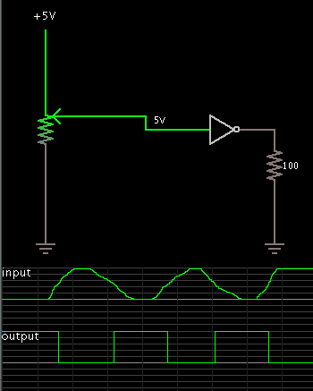
I will not be able to find out the inputs thresholds voltage level of the IC chips input If I supply it with +5 volts, I need to know when the IC chip switch states at what input threshold voltage level
Supply +5 volts on the input will not tell me at what input threshold voltage level the IC chip is