bxmas13
Newbie level 2
I am trying to build a toy for my kid and I would like to add a digital display that he can adjust(make numbers change) with a rotary switch.
How would I accomplish this? I am a beginner, my only electronic experience is from my high school electronics class 15 years ago. I am willing to get my hands dirty and learn.
If this is too in depth for a beginner please feel free to let me know.
Here is the display I am talking about.
Thanks so much!
Added after 5 hours 34 minutes:
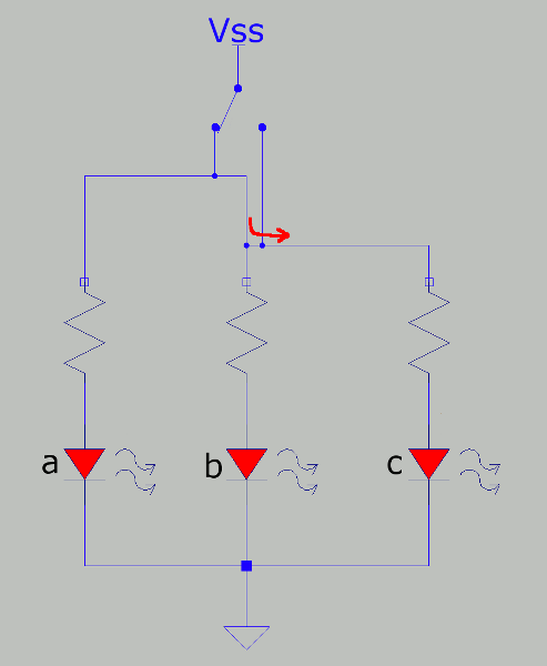
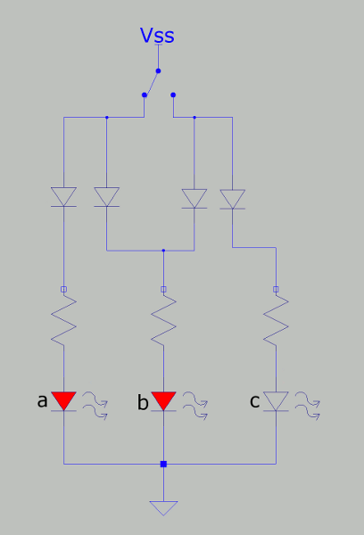
I think I found the answer. Get a 10 position rotary switch. On each position wire it so that it completes the circuit for each specific segment on the 7 segment display.
So in other words: position 1 gets wired to pins 'b' and 'c' to make the number 1.
position 2 gets wired to a, b, g, e, d and so on.
That sound right?

How would I accomplish this? I am a beginner, my only electronic experience is from my high school electronics class 15 years ago.
I am willing to get my hands dirty and learn.If this is too in depth for a beginner please feel free to let me know.
Here is the display I am talking about.
Thanks so much!
Added after 5 hours 34 minutes:
I think I found the answer. Get a 10 position rotary switch. On each position wire it so that it completes the circuit for each specific segment on the 7 segment display.
So in other words: position 1 gets wired to pins 'b' and 'c' to make the number 1.
position 2 gets wired to a, b, g, e, d and so on.
That sound right?