Continue to Site

Welcome to EDAboard.com

Welcome to our site! EDAboard.com is an international Electronics Discussion Forum focused on EDA software, circuits, schematics, books, theory, papers, asic, pld, 8051, DSP, Network, RF, Analog Design, PCB, Service Manuals... and a whole lot more! To participate you need to register. Registration is free. Click here to register now.

Difficulty in putting transconductance value in ideal VCCS 'G' in PSPICE.

Status
Not open for further replies.

viperpaki007

Full Member level 5
Joined
Jul 2, 2008
Messages
270
Helped
11
Reputation
22
Reaction score
8
Trophy points
1,298
Location
Finland
Activity points
3,395
Hi All,

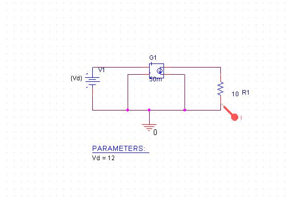
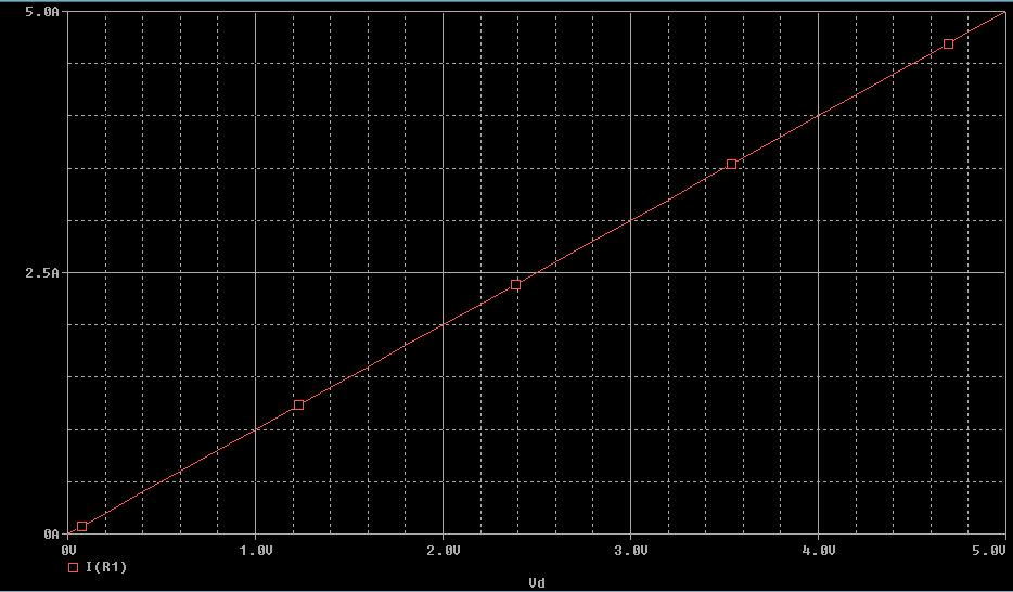
I am trying to use VCCS source in PSPICE with specified transconductance value of 50mS. I am using component 'G' in Pspice for that. The problem is, although i am putting 50mS in value column of 'G', it still simulates the circuit with transconductance =1S. I don't know what is the reason. Am i using the right component?

looking forward for your comments

regards
 

It should work. Are you putting 0.05 or 50m as the transconductance (not 50ms)?

Keith.
 

Attachments

  • VCCS.pdf
    4 KB · Views: 111

Hi,

Please look at my test circuit and simulation result. It is still showing transconductance of 1S
 

Could you post the netlist you get from the circuit? The circuit certainly looks correct.

Keith
 

It is still showing transconductance of 1S
Looks like. But it's surely not a general PSPICE problem. You may want to inspect the generated netlist. Or post the project files.
 

Check if you have defined the G device parameter appropriately.
Following circuit should give you desired result

v1 1 0 12
G1 2 0 0 1 50m
R1 2 0 1
.DC LIN v1 0 10 1
.probe
.end
 
In my PSpice version (9.2) there is only one ABM model for a VCCS that is called by GVALUE.
Which version are you using?

---------- Post added at 15:53 ---------- Previous post was at 15:44 ----------

The corresponding line in the netlist looks like this:
G_G1 $N_0001 0 VALUE { V($N_0002, 0)*50m }
 
I thought the VCCS (G source) had 4 nodes, two in, two out. Your line only has two nodes. I cannot check the Pspice documentation at the moment but maybe you can?

Keith
 
I thought the VCCS (G source) had 4 nodes, two in, two out. Your line only has two nodes. I cannot check the Pspice documentation at the moment but maybe you can?

Keith

No, it has 4 nodes.
Both output nodes are given directly with the name of the model ($N_001 and 0) and both input nodes are given with the voltage difference (between nodes $N_002 and 0) to be multiplied by 50m.
 

Yes, my mistake. I was only looking at the first part and reading it like the Hspice syntax.

Keith
 

Status
Not open for further replies.

Similar threads

Part and Inventory Search

Welcome to EDABoard.com

Sponsor

Back
Top