Continue to Site

Welcome to EDAboard.com

Welcome to our site! EDAboard.com is an international Electronics Discussion Forum focused on EDA software, circuits, schematics, books, theory, papers, asic, pld, 8051, DSP, Network, RF, Analog Design, PCB, Service Manuals... and a whole lot more! To participate you need to register. Registration is free. Click here to register now.

Different ways of doing Current sense transformer reset?

Status
Not open for further replies.

cupoftea

Advanced Member level 5
Joined
Jun 13, 2021
Messages
2,611
Helped
54
Reputation
108
Reaction score
115
Trophy points
63
Activity points
13,685
Hi,
We are doing a 750W Buck, 42Vin to 24Vout.
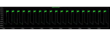
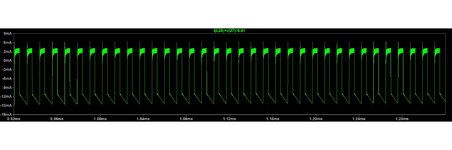
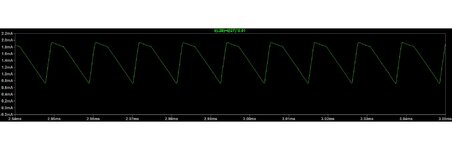
It has Current transformer sense (as attached). We note the attached two methods of doing the current sense transformer reset as attached. The simple one, with just the diode and Zener, has lower peak magnetising current in the CST secondary, and so appears better. So why do people ever use the other method for CST reset? (the one with the PNP)

PDF schems and LTspice sims attached ...also the CST secondary magnetising current waveforms are shown.
 

Attachments

  • Buck with higher magnetising current CST.pdf
    171.2 KB · Views: 225
  • Buck with lower magnetising current CST.pdf
    175.5 KB · Views: 200
  • High magnetising current CST.zip
    3.1 KB · Views: 130
  • Low magnetising current CST.zip
    3 KB · Views: 107
  • Higher magnetising current.jpg
    Higher magnetising current.jpg
    89.8 KB · Views: 151
  • Lower magnetising current.jpg
    Lower magnetising current.jpg
    85.9 KB · Views: 153

I'm assuming the circuit with the PNP is a basic forced-reset circuit (normally it's just a resistor to, maybe there's some benefit to using a regulated current source).

In the basic self-reset circuit, the energy to reset the core needs to come from the magnetizing current. If the magnetizing current is small, but the parasitic capacitance across the secondary is large, the magnetizing energy may not be sufficient to swing the secondary voltage and reset the core.

Forced reset circuits just guarantee that there's always some minimal amount of current available to overcome parasitic capacitance. I've never run into this issue myself, so I never implemented a forced reset circuit. But it's worth checking for during simulation and design verification.
 
If the magnetizing current is small, but the parasitic capacitance across the secondary is large, the magnetizing energy may not be sufficient to swing the secondary voltage and reset the core.
Thanks, it seems difficult to believe that the stray capacitance of the CST secondary could be so high that a normal diode_zener reset circuit woudlnt be able to work. Also, if the magnetizing current is small, then surely its easier for it to go back to zero and thus result in transformer reset?

Presumably you could measure the stray capacitance of the secondary by some sort of resonance technique...eg put the sec in series with a resistor and put that circuit across a square wave volt source and look at the ringing frequency at the edges..
 
Last edited:

I'm assuming the circuit with the PNP is a basic forced-reset circuit (normally it's just a resistor to, maybe there's some benefit to using a regulated current source).
Thanks yes, the PNP current source certainly keeps the level of magnetising current lower when there is significant secondary stray capacitance. (As the attached tow LTspice sims show). So both techniques reset the transformer fine, just that the overall level of the magnetising current is less with the current source method......and this situation is seen especially when there is significant stray sec capacitance.

Significant stray sec capacitance is obviosuly a significant problem in CST's and it makes me wonder why the sec stray capaitance isnt always written on the CST datasheet?....after all, it really increases the sec magnetising current.
 

Attachments

  • Buck with current source CST.zip
    3.2 KB · Views: 119
  • Buck with standard CST.zip
    3 KB · Views: 100
Last edited:

Thanks yes, the PNP current source certainly keeps the level of magnetising current lower when there is significant secondary stray capacitance.
The emphasis is on "when". Normally it isn't.
 
Thanks, so i am wondering why this power supply i am looking at has bothered to do a PNP current source in the CST circuit...?...when just a zener/diode reset would have sufficed.

But yes, no CST transformers ever state the stray secondary capacitance....
..Any guesses as to the general level of stray secondary capacitance for the featured item above, much appreciated?
 

The attached simulation shows how the leakage inductance must be factored in when designign a CST. With a typical coupling factor of 0.9 (likely for a CST) , then he attached CST has peak magnetising current of 35mA....whereas its only 1.4mA if the coupling factor is taken as unity.
 

Attachments

  • Buck CST with leakage.zip
    3.4 KB · Views: 88

does that reset ckt with the pnp even work ?
Thanks, sorry about this, but ive just realised i named the schematics the wrong way round in the top post, and in post #4, my "imitation 3V zener diode" is wrong. (unfortunately LTspice does not contain any zener diodes below 4V7). Thanks for helping me to see this.

Please find the corrected version attached here.

..I believe it does work, the secondary voltage can fly up to reset the transformer, and is clamped by the path through the PNP collector_to_base, and then through the "zener" in forward direction, and then through the 51R, and then through to the 12v voltage source.
--- Updated ---

Then again, i am wondering, because LTspice is showing the CST resetting just fine, with nothing more to reset the CST than a 100pF cap across the secondary.
 

Attachments

  • CST with current source.pdf
    175.9 KB · Views: 165
  • CST with current source.zip
    3.2 KB · Views: 95
Last edited:

do you have a reference for the pnp reset ckt ?
Sorry unfortunately not...this is from a schematic of a power supply that we got sent that was not working. (incidentally, it just needed its fans changing) The power supply is from a different vendor, who has now closed down......so we have the power supply, and indeed the schematics for it, but its not one that we sell, so we know nothing else about it.....just that this is its CST reset circuit.
The company tell us that this power supply has a large number of units already in the field that have worked fine for 10 years plus...we believe this, since we know that customer.

I must admit, this "PNP reset circuit" is a new one on me....i am a bit uncomfortable with the clamping path including the PN junction of the Collector_base of the PNP.....i didnt think it was right to put much current through that junction in that direction? The PNP they use is a 2N2907.


Regarding this "PNP reset circuit", I can see that it does advantageously make current flow in the secondary coil, such that the magnetising current peak is a little less than otherwise....but its such a pifflingly small amount of improvement that it seems not worth it. -And so why not just use the standard diode/zener reset circuit?........i mean, as you know, because such 100:1 CST's obviously contain 100 turns, and so need the space for 100 turns, then they always tend to use a bigger core than saturation current would dictate....so when you've got all that saturation "headroom", why bother with the "PNP reset circuit"?
 
Last edited:

The thing is, that this high magnetising current (which occurs when leakage inductance is high), can be offset with the PNP current source as in the attached (if the current source provides sufficient 'offset current'). This significantly reduces the peak magnetising current. The LTspice sim demo's this.
Why is it that nobody uses this "PNP magnetising current reducer" circuit?

Do people (generally) like "living life on the edge", and being close to the risk of CST (Current Sense Transformer) saturation? If so, then i can understand why they dont use the PNP circuit.
 

Attachments

  • Buck with offset magnetising current in CST.pdf
    179.3 KB · Views: 113
  • offset magnetising current with current source.jpg
    offset magnetising current with current source.jpg
    111.1 KB · Views: 126
  • Buck with offset magnetising current in CST.zip
    3.4 KB · Views: 90

You actually need to tune the circuit to suggest a justification for the reset circuit. But arbitrary low coupling of 0.9 doesn't describe a typical CT.

I'd suggest to take an off-the-shelf CT and check if there's any saturation problem in a reasonably designed application circuit. The fact that the circuit was found in a series product proves nothing. The designer might just show a preference for over-engineering.
 
But arbitrary low coupling of 0.9 doesn't describe a typical CT.
Thanks, thsi was discussed inconclusively here...

The last post discusses why pri/sec coupling would be poor in a current sense transformer.
If we consider that best coupling is obtained by bifilar winding of primary and secondary (with equal number of turns for pri and sec)...then we note that the 100:1 current sense transformer is about as far away from this as can be.....as such, i postulate very poor coupling for a current sense transformer......this was discussed several years ago on edaboard, and i am seeking the thread....i remember mtwieg also very kindly had some input to it.
 

I haven't measured the coupling on a CT for power electronics for a while - but the symmetry of fields suggests it will be higher than 0.95 - I will measure some typ examples next year ....
--- Updated ---

Often - for high speed - no reset ckt is used - and as long as the diode can handle the reverse volts and the cap of the diode and wdg is low enough - reset can be quite quick at 100V or so reverse generated by the CT itself - there will be a limit on rise time of reset volts due to the wdg cap - and diode cap ....
 
Often - for high speed - no reset ckt is used - and as long as the diode can handle the reverse volts and the cap of the diode and wdg is low enough - reset can be quite quick at 100V or so reverse generated by the CT itself - there will be a limit on rise time of reset volts due to the wdg cap - and diode cap ....
Thanks, this seems like a good idea for PFC stages, where the duty cycle can be very high. Then again, it does seem a little risky, kind of relying on the stray capacitances to limit the voltage rise to within the diodes Vrev max.

Also, as you know, even if k=0.95, the secondary referred magnetising current is still some 15mA peak.....a lot higher than the 1.4mA peak you get with k=1 (as the attached shows)
 

Attachments

  • CST magnetising current k = 0.95.jpg
    CST magnetising current k = 0.95.jpg
    139.8 KB · Views: 79
Last edited:

This Unitrode/TI application nodes is narrowing the range where reset circuits may be actually required https://www.ti.com/lit/an/slua174/slua174.pdf

I'd ask about CT saturation characteristic, expectable duty cycle and CT termination before I think about dedicated reset circuits.
 
Thanks FvM, thats a great article on this subject...its interesting though, that at the bottom of the LHS column of page 1, it says that the leakage inductance is "generally not a problem"....which , by the sims shown above, we know is not correct.
 

it is very easy to measure the the leakages, and L on the LV side, and the SRF, this gives the cap on the LV side, the SRF also gives you the reset time,

from this you can determine what the max D can be maintained on the CT, with simple reset.
 
Leakage inductance increases the AC core flux because it causes an additional voltage drop between secondary winding terminals and inner transformer voltage. An exact analysis must factor in the asymmetrical distribution of leakage inductance between primary and secondary of a typical toroidal current transformer. It's not considered in your simulation which overestimates the leakage effect on core magnetisation.

A certain amount of additional AC flux due to leakage is normal CT operation, the part is designed to deal with it. Some CT are even prepared for DC magnetisation.
 
Status
Not open for further replies.

Part and Inventory Search

Welcome to EDABoard.com

Sponsor

Back
Top