Continue to Site

Welcome to EDAboard.com

Welcome to our site! EDAboard.com is an international Electronics Discussion Forum focused on EDA software, circuits, schematics, books, theory, papers, asic, pld, 8051, DSP, Network, RF, Analog Design, PCB, Service Manuals... and a whole lot more! To participate you need to register. Registration is free. Click here to register now.

[PIC] Difference in two similar LDR Characteristic

Status
Not open for further replies.

ecaits

Member level 4
Joined
Jan 16, 2014
Messages
76
Helped
0
Reputation
0
Reaction score
0
Trophy points
6
Activity points
579
Difference in two similar LDR Characteristic in two axis sun tracking system

Dear Friends,

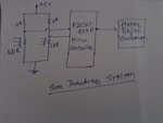
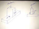
I am working on sun tracking system in which I am using two similar LDR to sense the intensity of sun by shadow method.
But the characteristic of both similar LDR are different means at the same light intensity, both LDR shows different resistance.
By using voltage divider circuit, I will detect the analog signal and provide to micro controller for comparison and accordingly I will operate the motor drive.

To solve the issue I need to use two similar LDR which have same characteristic.

Can anyone suggest me the LDR which have same characteristic or any other option?

Plz find the attached images for reference.

Thanks,
 

Attachments

  • Block Diagram.jpg
    Block Diagram.jpg
    1.5 MB · Views: 109
  • Two Similar LDR.jpg
    Two Similar LDR.jpg
    1.1 MB · Views: 89
Last edited:

Re: Difference in two similar LDR Characteristic in two axis sun tracking system

Does the LDR, have a wide tolerance? Max/Min= 2 or typ +/->50%
This can lead to tracking errors as does dust coverage.

Ideas.

SFH series Silicon photo diodes are much more precise, low cost, but smaller and thus higher impedance. ( but more consistent A/W)

I don't know the tolerance but suggest few % is possible, but not spec'd.

Viewing angle is not always adequate so parallel diodes can be used, spaced X deg apart.

For X azimuth angle detection and ignore Y angle, you can consider blocking stray light in Y axis to permit season variation only. You have options for optical diodes or IR only with daylight blocking filter. Consider any source of light interference and aging factors from dust and wind direction how it affects tracking.

Consider how solar input and shadow object affect differential gain as energy levels are not always constant. Decide on minimum hysteresis threshold as a function of photon power.

You might toss the shadow effect and consider parallel array of three PD 30deg sources pointing East with angle spacing to match 50% theta and same pointing West, then you have two 90 Deg arrays to measure differential on bridge for East West. Stray light from sides needs to be plotted to linearize the azimuth angle detection. Lens shape is a major consideration.

In the LDR shadow approach, the contrast of the shadow and size of the LDR affects the response.
In the PD approach the angle of the lens with array and orientation determines the response. Modeling is required to make it linear.

Another method is a linear solar PD array with a slit to measure solar azimuth but requires decoding the maximum. sensor and correlation between mounting angle, size and height of slot and solar position.

The another precise method uses a solar clock geometry to create the shadow on the semi- circular PD array to locate the shadow.

The main thing is to avoid hunting and wasting power in order to gain a small advantage in efficiency.
 

Status
Not open for further replies.

Similar threads

Part and Inventory Search

Welcome to EDABoard.com

Sponsor

Back
Top