Continue to Site

Welcome to EDAboard.com

Welcome to our site! EDAboard.com is an international Electronics Discussion Forum focused on EDA software, circuits, schematics, books, theory, papers, asic, pld, 8051, DSP, Network, RF, Analog Design, PCB, Service Manuals... and a whole lot more! To participate you need to register. Registration is free. Click here to register now.

[SOLVED] Difference between an MPPT solar charge controller and an ordinary charge controller

Status
Not open for further replies.

ashare

Newbie level 6
Joined
Mar 31, 2011
Messages
12
Helped
0
Reputation
0
Reaction score
0
Trophy points
1,281
Activity points
1,412
Hi Everyone,

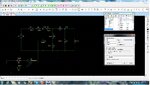
I have been reading about MPPT charge controllers and their advantages over ordinary ones (PWM based??). My question is how is an MPPT charge controller superior than a buck-boost (BB) converter chip or for that matter any converter chip? The MPPT algorithm takes in parameters like input current and input voltage and calculates the power successively and compares with the previous reading. The BB controllers also have feedback in the output which regulates the voltage at the load and the load draws as much current it requires from the circuit (based on current limits set). Based on the current mode and voltage mode feedback, the power switch's duty cycle is varied in a BB converter as well. Doesn't MPPT also vary the duty cycle of the power switch in a similar manner. How is it maximizing power from the panel by doing so. Please let me know, if my question lacks clarity.

Thank You.

Regards,
ashare
 

You need to study the photovoltaic panel itself before the charge controller. Briefly: As current is drawn from the panel, the panel voltage drops, not necessarily in a linear fashion. So, there will be a point (voltage, current) at which the maximum power is transferred; where P=IV is a maximum. As the illumination changes, this point changes, so the circuit cannot be designed for a static maximum power point. Likewise there are changes as the panel ages.

The MPPT controller uses an algorithm to determine and use the optimum power of the panel. It dynamically adjusts the switching regulator's use of current to keep the power transfer at a maximum as all these things change. A BB regulator simply provides a constant output voltage without regard for controlling its use of input power.

I understand your first point clearly. What confuses me is the second. Assuming that there is a deeply discharged 12V lead acid battery battery at the load, and assuming that it requires 13.6 V to charge and it takes 3A continuous current to charge. The power requirement at the output is 40.8. Also we have a panel of 50W with 18Vmp. Had the panel been directly connected to the battery, the panel would be supplying a lower current as it will be at battery voltage. However assuming we use a BB converter (one of those chips from TI) would it still be required to track the MPP? The converter can manage to maintain the 13.6V at it's output irrespective of the input variations. Am I missing something?
 

MPPT and PWM are complete different things. So you can't say which one is better.

PWM (Pulse Width Modulation) is just a method that can be used in converters (mains supplies, chargers, etc). Depending on converter topology (for example buck, flyback, forward), changing the duty cycle and or frequency changes output voltage or current.

MPPT is a higher level method to find a convenient electrical load for the solar cell so that it provides maximum power. The MPPT controller controls the power converter. The power converter may be PWM based.


MPPT can be done by try and error. Change the duty cycle or frequency of the converter so that the batteries receive more current. When the current drops (instead of raises), you need to steer the duty cycle or frequency in opposite direction. When doing this continuously, you will always draw maximum power from the solar cell system.

So a MPPT power converter chip consists of whatever power converter controller (PWM, frequency, hysteric, etc controller + current/voltage sensing + mosfet driver) and a circuitry that constantly changes the voltage or current setting so that maximum power is drawn from the solar cells.
 

... and a circuitry that constantly changes the voltage or current setting so that maximum power is drawn from the solar cells.

Thanks for your kind reply. Could you elaborate on the quoted text above. As per my understanding, the only thing which can be changed by altering the duty cycle of the power switch is the output voltage. The current drawn is determined by the SoC of the battery. The batteries which are required to be charged have some voltage regulation to be met, hence there is very less scope of playing around with the output voltage to vary the power at the output. We cannot increase the power drawn by the load. Is there any method to pull up the panel voltage? I assume panel voltage is set by parameters which are beyond our control. By taking all these things into consideration, how can we interpret that MPPT algorithm improves efficiency?

Regards,
ashare
 

Of course, you can't always operate on maximum power point. When the batteries (lead acid) have reasonable charge, you can't further increase the voltage to get more charging current, as this will lead to gassing and shorted battery life. One of the options you have to still operate at maximum power is to switch to another bank of batteries that need charge, or heat stones that can be used to warm the house during cold nights.. If you frequently run in a power surplus, you need to add more batteries.

I don't see the relation between MPPT and higher panel voltage, could you further explain?

Regarding efficiency increase due to MPPT. If you can store, or use the power, MPPT will get the most out of your panel given certain light intensity. It will do that over a broad range of light intensity.

It has virtually no use to install a system with MPPT if the panel can provide 10 kW, but your load + batteries can accept only 2 kW. A less optimum system, but with more batteries will perform better.
 
  • Like
Reactions: ashare

    ashare

    Points: 2
    Helpful Answer Positive Rating
Please see the attached image. It is an excerpt from Microchip App note AN1521 for implementing MPPT. It's mentioned that panel voltage is modified by changing the duty cycle. I didn't completely understand this though. It could be that the DC-DC converter is providing an impedance match to tap the max power out of it. However, we know that changing the duty cycle changes the output voltage. How does this help in achieving regulation at the output and improved power extraction from the panel at the same time?
 

Attachments

  • MPPT.jpg
    MPPT.jpg
    123 KB · Views: 193

Instead of looking to output current and voltage, you can also look to the input voltage and current (that is power delivered by the panel).

You are right, you can see the converter as an impedance transformer.

If you consider a PWM buck (step down) converter: Vout = d*Vin, Iout = Iin/d (d = duty cycle), hence Rin = Rload/d^2 (this is your impedance transformation). Rin is the load as seen by the solar panel

If you reduce d, Rin increases, hence the panel voltage, as the panel has to provide less current. By adding small changes to d, one can find the value for d that gives the largest product of Vin*Iin. Vin and Iin are the panel output voltage and panel output current. As long as the output voltage of the converter is below the maximum charging voltage for the batteries, you can use MPPT. If not, the duty cycle needs to be limited to a certain maximum to avoid excessive output voltage. So you need to add an additional decision block in the loop that says: Vout(converter) > Vmax -> reduce duty cycle.

You may even need an additional decision block: Iout(converter) > Imaxcharge -> reduce duty cycle. This loop is required when at maximum light intensity, and no additional load, the converter's output current exceeds the maximum charge current for your batteries. Other option is to install so much batteries, that you will never exceed the maximum charge current for each battery.

When the required output voltage of the converter is always lower then the solar panel output voltage at MPPT at light intensity that still provide usefull output power, you can use the buck topology. If the required output voltage can be higher then the panel output voltage you may need a buck-boost (or boost) topology.
 
Thank you. That cleared my doubt. I really appreciate your patience! :)
 

The #8 Post also cleared my doubt .... correct me if I am wrong ....
1.Say I have designed buck converter to charge 12v battery ...and I am using the P&O algorithm in input side of converter to extract maximum power from solar panel ,but the catch is ,by doing so (i.e,implementing this algorithm) it also varies the output voltage of converter ...We have to see to that it does not go above the rated charging voltage of the battery specified by manufacturer...i.e, Say Eg, even if changing or increasing the duty cycle may lead to more power extraction than before ...we cannot do it because it may end up increasing the rated output voltage for charging the battery (i.e output of converter)......
Am I correct?

Hi Akash,

That is my understanding as well. Let's hope 'WimRFP' replies to your query.

Regards,
Ashare
 

Yes hope I get my confirmation......
I am now working on a sepic based converter and currently simulating in NL5 ....I am still not sure how to regulate the output voltage with pwm .....
I used the design from this website..**broken link removed**
I set the output to 14v to charge 12v battery ...the input variation is from 8v to 25v range ...
It shows to use a duty cycle between 36% to 64% ...I think it means I have to track MPP within that range .
The output is not quit what I expected ,it seems to go till 40v also...
Please help...
 

@Akashmd: You are correct, When you are operating at MPP for you solar cell and the battery charging voltage exceed the maximum for long-life, you need to reduce d so that the charge voltage drops. The same is valid for excessive charging current.

When you draw too much current from the solar cell so that you are outside MPP setting, both charge voltage and current will increase when reducing d. When you further reduce d, charge voltage and current will reduce. Normally this behavior should not happen, as when you implement MPPT, you will operate at MPP. Make sure that you software "knows" what to do when the charging voltage increases a little when reducing d (just further reduce d).

Unexpected things may happen when for example a large plane shaddow slides over the solare cell. Then the solar cell may operate short time outside MPP because of settling time of the algoritm.
 
Is it Ok to charge 12 v battery with 14 v ....Further I am using sepic converter to charge battery.
Please can you tell that my sepic converter works for mppt ...
The design has its input variable from 8 v - 25 v...should I fix the output to 14 v to charge the battery and use mppt algorithm??
I am using NL5 simulation....frequency is 64Khz...duty cycle from 36% - 64%...
If input is 8 v and I set duty cycle to 64%, I get output as appx 14 v.
If input is 25 v and I set duty cycle to 36%, I get output as appx 14 v.
So to say ,buck and boost are both working ....So I have to implement mppt algorithm for duty cycle control which is in the range of 36% - 64% ? and also have to watch output does not exceed 14v??
In simulation ,if I set input to 25 v and if duty cycle is 64% ,I get 40 v output which is not so good for Mr. Battery...:roll::x
Please solve my doubts ...I think many will have the same doubts...
I will give the attachments of simulation....
 

As I understand it:

* As soon as you connect a battery to the converter, the output voltage automatically becomes the battery voltage.

* 14.4 V is the customary maximum level to which to charge a 12V lead-acid battery (although this varies depending on a few things such as temperature).

* During the time battery voltage is below 13.8 V or so, your converter should adjust duty cycle so that current going into the battery is at a safe level. Above 13.8 V, your converter should taper down current, so it is zero as battery voltage approaches 14.4 V.
 

As I said my septic converter can go up to 40 v..how to set output then?If I say output should not increase above 14v when connected , so it means when I use mppt algorithm and connect output of converter to battery,then the voltage will read 14v ....am I correct...there is so much confusion.....
 

The electrical pulses generated by a switched coil converter are not necessarily at any particular volt level (unless you regulate it, but for the moment let's talk about the raw output, unregulated).

Output voltage depends on the load.

If load R is low, then output A will be high, and V will be low.

If load R is high, then output A will be low, and V will be high. It might get so high that a spark occurs. That is the nature of an inductor.

A smoothing capacitor averages the output pulses. The voltage settles to a level which depends on the load.

And a battery sets the output voltage to its own voltage. As the battery charges this volt level rises. It might start at 11 V, and gradually go up to 14 or 15 (or higher if you overcharge it).

Although I have no direct experience with an MPPT, I had several years of experience with PV panels, a battery bank, and power inverter.

The charge controller (or MPPT) should stop charging a 12V battery when it reaches 14.4 V (subject to wisdon gained with experience with the equipment).

I tested my PV panels. Each was made with enough cells so that it put out a maximum of 23V, with no load. I'm pretty sure the manufacturer determined this by experimentation. I think they connected various numbers of solar cells in series, until they found the most efficient number of cells, to charge a 12 V battery. However I never saw the battery voltage reach 23 V.

As I understand it, the MPPT's purpose is to convert the juice soming from the PV panel, so as to push the maximum current into the battery. (If it is designed properly, the MPPT will limit the current to a safe rate as required depending on the battery.)

So it is not necessarily rigid, as to what output voltage the MPPT produces, or is set to produce.
 
Ok thank ...I think that helped me a little "So it is not necessarily rigid, as to what output voltage the MPPT produces, or is set to produce"
I was wondering how to control two parameters at once....What you said was true "If load R is low, then output A will be high, and V will be low.

If load R is high, then output A will be low, and V will be high. It might get so high that a spark occurs. That is the nature of an inductor."
This is because as I reduced load resistance to 15 ohms , output became max 40 v....
And if the load resistor was set to 50 ohms ,output would go beyond 110v or even 150v.....
So now the question is what is the battery resistance ...?I know it very low...but it is also a variable I guess...!!Another twist??..What more should I consider ?Am I missing something??
 

Attachments

  • Sepic1 - Copy.jpg
    Sepic1 - Copy.jpg
    475.9 KB · Views: 171

This is because as I reduced load resistance to 15 ohms , output became max 40 v....
And if the load resistor was set to 50 ohms ,output would go beyond 110v or even 150v.....

Once you hook up the battery, the output voltage never goes below battery voltage. It is not possible to measure directly the voltage coming from the converter. All you know is that if the battery is charging, the converter has a higher output voltage than the battery.


So now the question is what is the battery resistance ...?I know it very low...but it is also a variable I guess...!!Another twist??..What more should I consider ?Am I missing something??

Correct, battery resistance is low.
Battery voltage may develop a bit of ripple, as pulses of current come from your converter.

Your schematic has resistors with very low ohm value. These are conveniently located where you can monitor current through them. Your sepic converter is supposed to monitor the voltage across those resistors, and control its duty cycle, so that it maximizes battery charging current (as its general purpose).

To do this, your sepic converter needs a smart control circuit.
 
What did you mean by monitor voltage across those resistors ??Does it mean battery voltage ...?Smart control circuit in the sense..?What is it?..Then what about algorithm for duty cycle ?...Can I add a Zener diode across output...will it help me to see that battery voltage cannot go beyond certain point??
 

Status
Not open for further replies.

Similar threads

Part and Inventory Search

Welcome to EDABoard.com

Sponsor

Back
Top