signalflow
Newbie level 5

- Joined
- Nov 15, 2013
- Messages
- 9
- Helped
- 0
- Reputation
- 0
- Reaction score
- 0
- Trophy points
- 1
- Activity points
- 118
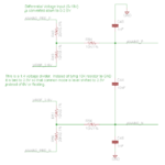
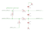
I am trying to use the ADS1241 ADC with differential inputs. I attached 2 circuits (one is for a voltage input and another is for a current input).
I am a little confused on the input voltage range of the ADS1241. Datasheet pg. 3 says Analog Input Range (Max=AVdd+0.1 and Min=AGnd-0.1) but then it says Full-Scale Input Range (In+ - In-) = +/-Vref/PGA where PGA is the gain of the amp. The Vref=2.5V. I have Vref- gnded so I only have a positive Vref. So I am confused if the input voltage range is 0-5V or 0-2.5V.
For my voltage input, I used a voltage divider to convert 0-10V down to 0-2.5V. But instead of referencing the voltage divider to GND, I referenced it to 2.5V. That puts the common mode voltage at 2.5V (right?).
For the current input, I used a sense resistor (R29) to convert the current to voltage and also tied the negative input to 2.5V through a 1Mohm resistor to set the common mode voltage at 2.5V.
I believe this allows me to read positive and negative currents.
The other resistors and capacitors are low pass filters for common mode voltage and differential mode voltage.
Any help is appreciated as I just am not sure I have this right. I am a little rusty in this area.
Thanks!


