Salvador12
Full Member level 4
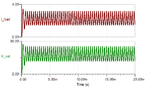
surely a scope is needed and my friend hes an old electrician has one we actually measured the gate waveforms with the old transformer arrangement and they were nice. i actually have a 7815 regulator to be sure i have some headroom.also i have reostats for deadtime and frequency , i have increased the deadtime resistance a bit bigger than what is used in the schematic to give me some safety.
well I doubt the transformer rearrangement directly caused the fets to go bad.
I think the heat is to blame for their destruction , the question is were did the heat came from , most likely overcurrent in the primary because previously the fets were dead cold yet the secondary voltage decreased upon a heavy load and the maximum output power was never higher than about 500w, ususlly less from my voltage and resistance calculations , this time under the same load the secondary voltage didint drop one bit.
maybe i should just disconnect the feedback IC? well i will ge new parts and measure the supply voltage under the same load , im talking about the IC supply voltage from the 15 volt regulator , if it will be about 15 volts or close i can assume even without scope that the waveforms are good.
still i wonder what made them so hot , if they would have had shootthrough I think they would ahev destroyed themselves alot faster and with enough deadtime it shouldn't be the case, prety much im thinking either overcurrent or somehow they were driven not fully open , but if im correct mosfet's gate capacitance doesnt increase with high load on the drain source channel does it ? and if it doesnt then why suddenly the IC's couldnt drive the mosftets nicely if they did so before all the time.