Antennas Work Germany
Newbie
Hello all!
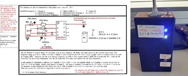
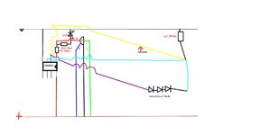
Is there a way to amplify the signal so that 8m rx 16m or more meters could become? (An additional circuit diagram would be great. Or 2 amplifiers in series, but which op fits the LM358P? The RF Diode - Bat 62 (Up to GHz or BAT 15) work very well at 2.4 GHz, but also in the VHF / UHF range depending on the antenna, or its length. I have 2 antennas built in, once a quad 4 * 3.12 cm and a Wifi Pi antenna for 2.4 GHz SMA socket. Switch antenna 1 + 2. So you can switch between only wii rx and HF Distinguish fields. Circuits are often published on the www that don't work at all, and such circuits should be deleted. The circuits in particular are shown on Youtube, but are sometimes built upside down, which is why there are errors in circuits during construction. Or circuits that don't make any sense, or not working properly.
Here is a video of the HF detector: