PG1995
Full Member level 5
Hi ")
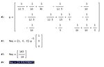
I was having a look on the "Example 2.15" which you can see in the following link: https://img23.imageshack.us/img23/5218/deltawye.jpg
1: I don't understand how "abn" form a delta configuration. For example, take the case of "can" configuration. We start at 'c' and traverse through 12.5Ω resistor toward 'a', and then from 'a' we traverse through 10Ω and 5Ω resistors and end up at 'c' where we started the traversing. It is a "can" delta configuration. But what is happening in case "abn" deta - which in my view is not a delta? Please help.
2: Now consider the statement which I have highlighted: Another approach would be to solve for the equivalent resistance by injecting one amp... Chap 4.
In Chap 4, which we haven't covered so far, the author introduces these topics: Linearity Property, Superposition, Source Transformation, Thevenin's Theorem, Norton's Theorem, Maximum Power Transfer.
Which of the above theory/topic the author would have used to solve the problem in "Example 2.15" instead of detal-wye appraoch? Please tell me.
Thank you for your help and time.