Continue to Site

Welcome to EDAboard.com

Welcome to our site! EDAboard.com is an international Electronics Discussion Forum focused on EDA software, circuits, schematics, books, theory, papers, asic, pld, 8051, DSP, Network, RF, Analog Design, PCB, Service Manuals... and a whole lot more! To participate you need to register. Registration is free. Click here to register now.

Designing PIFA shorting Pin in HFSS

Status
Not open for further replies.

PauloF91

Newbie level 4
Newbie level 4
Joined
Jun 18, 2013
Messages
7
Helped
0
Reputation
0
Reaction score
0
Trophy points
1
Visit site
Activity points
65
Hello,

my problem is as simple as it can be. I just wanna design a PIFA shorting Pin. I'm starting to study antennas, I'm really new at this.
I'm aware of wavelength formula,if I got my L1 + L2 to be a quarter wavelength, I got it resonant to my frequency, is that right? I find it too easy and insanely small.

f = 2,4Ghz -> wavelength/4 = C / ( 4 * f * sqrt(Er) ) = 14.9 mm

So, L1 + L2 = 14.9 mm.
And, can I really follow this layout?
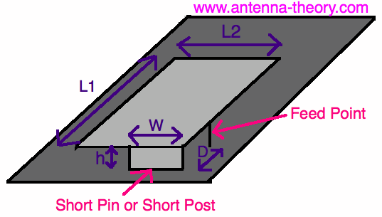
pifas.gif


And btw, I'm following Ansoft HFSS Antenna Design Kit, I'm starting from there. If I implement it for this frequency, once I run "Analize all" my resonant frequency appears as around 7Ghz (more or less) instead of my 2,4Ghz, can someone guess why? I got substrate properties done right.

Thanks in advance.
 

The layout shown, can result in a good antenna when measures are well chosen.

The resonance at 7 GHz is likely due to a higher resonating mode. For example a quarter wave whip that is resonant at say 300 MHz, can also resonate in a 3/4 wavelength mode (around 900 MHz), but the radiation pattern is different. You can see this from the current distribution in the patch.

Your resonant frequency may be lower (then 2.45 GHz) depending on the width of the shorting strip. A narrow shorting strip results in lower resonant frequency and less usefull bandwidth. The position of the feedpoint depends on the loss in your dielectric, and the heigth of the patch. Small heigth (h) results in small D to get 50 Ohms.

Without being offensive, if you really want to learn antennas, start with transmission lines, plane/spherical waves, radiation from current segments, total radiated power, reflecting properties of ground planes, etc. You are now learning how to enter recipe values in a software package.
 

Without being offensive, if you really want to learn antennas, start with transmission lines, plane/spherical waves, radiation from current segments, total radiated power, reflecting properties of ground planes, etc. You are now learning how to enter recipe values in a software package.

You're right, I know I should, but this is part of a project, I gotta get this done asap.

What you said made sense, since 2.4Ghz * 3 = 7.2Ghz, maybe that was the resonant frequency, but then, how do I make it resonant for 2.4? Cause in this case it is ONLY resonant to that frequency.

Do I triplicate my patch size?
And about the shorting pin: in hfss, this shorting pin is made out of a cone, not really a sheet. I think I'll just try to optimize it and bring my resonant frequency down to 2.4 and see what happens. The problem will be about the radiation pattern, but I'll see what I can do.
 

Can you start the simulation at a lower frequency and are you sure you set correct dielectric parameters? What is the height of the patch (in free space wavelength)?

To avoid confusion, can you post an image?
 

I set feedY as -patchY/2 but I'll optimize it later. Same for subX and subY.
Substrate is FR4. And Airbox is 4.0788 cm each side.


- - - Updated - - -
PS: I meant feedX, not feedY. Now it's 0, but I'll optimize it to get the right impedance. I believe there isn't a formula for that, am I right?

Cheers.
 
Last edited:

Regarding the Airbox, please check the documentation for that, as I don't know HFSS.

I can't figure out the size of the patch and feedpoint from the image provided. You have a thin shorting pin, this reduces the resonant frequency, expect it to be below what you expect based on the formula from your first posting (Your text: "So, L1 + L2 = 14.9 mm"). Set your start frequency below 2.45 GHz or reduce the patch size to find the lowest resonant frequency.

Does your feed has the same scale as the patch? your feed probe seems to be very large (diameter) compared to the patch size?
 

I can't figure out the size of the patch and feedpoint from the image provided.
Does your feed has the same scale as the patch? your feed probe seems to be very large (diameter) compared to the patch size?

The patch is square.
L1 = patchX (0.73cm) ;
L2 = patchY (patchX = 0.73cm) ;
L1 + L2 = 0.73 + 0.73 = 1.46 cm (quarter wavelength) <=> lambda/4 = C/(4*2.4GHz*sqrt(Er)) = 1.46 cm

My feed is supposed to be standard coaxial cable. the inner radius is 1.6mm, and the outer radius is 5.4mm. Not that small, it's the antenna itself that is already small.

- - - Updated - - -
I'll triplicate the patch size, theoretically, my resonant frequency will drop for 2.4GHz. My question is why it resonant for lambda*3/4 and how to make it resonant for lambda/4.

Cheers.
 
Last edited:

Given your thin vertical grounding pin (inductance), you can't rely on physical quarter wave resonance length, it will be shorter then that. You can also see it as an inductor (your vertical post/pin) with a capacitive top.

The patch looks very small compared to the 1.6mm coaxial inner conductor diameter. What is the lowest frequency you simulated, and how do you determine whether or not it is into resonance (it can be in the left or right part of the Smith chart). Did you enter a loss value for the dielectric?. If not, the first resonance (quarter wave mode) will be on the very right side of the Smith Chart.

If you found this resonance point, you need to place the feed closer to the vertical post, and need to readjust the patch size a bit. You may run into a situation that due to the size of your feed, you can't get a good VSWR.
 

The patch looks very small compared to the 1.6mm coaxial inner conductor diameter.
I'm just trying to follow my research. I see everywhere that L1+L2 has to be a quarter wavelength but according to the designing kit tool, L1+L2 will be even greater than the actual wavelength. I dont know which one should I follow.

What is the lowest frequency you simulated, and how do you determine whether or not it is into resonance (it can be in the left or right part of the Smith chart).
My frequency sweep goes from 1 to 8 GHz, if that's what you're asking. I don't even know what resonance means, I guess it's all about the response amplitude to the frequency sweep I set previously.

Did you enter a loss value for the dielectric?.
Yes, 0.02 .

If you found this resonance point, you need to place the feed closer to the vertical post, and need to readjust the patch size a bit. You may run into a situation that due to the size of your feed, you can't get a good VSWR.
According to my research, the distance between the feed point and the shorting pin will determine the impedance. The greater the distance is, the greater will be the impedance.

I just want a PIFA to work at 2.4GHz and be able to explain why. I don't know what can I rely on: if the designing kit tool, or my research.. and none of both will do, yet.
Nothing makes sense here...
 

the L1+L2 rule is just a bad indication. When, for example, W=L2, L1 is almost a quarter wave long, even when L2 is (for example) 0.1 lambda. As mentioned before, a very thin shorting pin, needs smaller patch size.

I would recommend you to reduce the size of you feed significantly so that you can move the center of the feed more close to the vertical shorting pin. Other option is to use a capacitive feed. If size is not that important I would increase W. It will result in larger L1.

I made several of these kind of patch antennas, but on low loss dielectric. The feed had to be very close to the vertical pin due to the high Q factor of the resonator. I even had situations where the feed was at the vertical pin. With your thick feed, you may not be able to find a good match.

Without knowledge of basic transmission line theory and AC circuit theory, you will not be able to explain why it works.

you mentioned: "according to the designing kit tool, L1+L2 will be even greater than the actual wavelength." For the smallest size antenna, this is not true. Of course you can make the patch large and rely on a higher propagation mode, but this is normally not done as this increases size, and changes the radiation pattern significantly.
 

the L1+L2 rule is just a bad indication. When, for example, W=L2, L1 is almost a quarter wave long, even when L2 is (for example) 0.1 lambda.
If size is not that important I would increase W.
Ye, I know, but since im talking about shorting pin, I assume W=0. The general rule I've read is actually an approximation and it's L1+L2-W+h = lambda/4, but you can neglect h and W=0. But I'm sure you know that :p

I would recommend you to reduce the size of you feed significantly so that you can move the center of the feed more close to the vertical shorting pin.
Yes, that has been kinda problem for me. But shouldn't it be universal? Anyway, i'll reduce it and see what happens.

What bugs me, is that I simply cannot get this done.. I've spent so much time reading stuff about this, but when it comes to simulations, nothing matchs..
this should be as simples as possible.
 

No, it is not as simple as possible. When you don't know the basics of resonators, effect of PCB meterial loss, loss due to radiation, etc, it can be an almost endless process of guessing. The second thing that can give problems is knowing how to use the simulator in the best way.

Regarding the shorting pin: that has inductance and has large influence on the size of to patch to get resonance at the desired frequency. It also modifies the voltage distribution along the complete structure and therefore it has also influence on the feedpoint position to get 50 Ohms.

If you don't know resonance, you very likely can't recognize the resonance points from the Smith chart, so you don't know how to modify the structure to get the job done.
 

Ok, I'm gonna start reading some books about it.

Thanks for the effort, I really appreciate that!
Cheers.

- - - Updated - - -

I got 3 books: «Antenna Theory» by Constantine A. Balanis; «Antenna and Radiowave Propagation» by Robert E. Collin; «Modern Antenna Design» by Thomas A. Milligan
Do you know any of these books? I think I'll go for the 3rd one.
 

Before starting with antennas, make sure you are familiar with LCR resonant circuit and transmission lines. Reason for that is that a large class of antennas are in fact transmission line resonators where most of the loss is due to radiation of EM power. It is also good to know how resonant behavior looks on a Smith Chart.

the resonant behavior is due to strong standing wave patterns in the antenna. The antenna conductors can be modelled as transmission lines or combination of transmission lines and lumped components (L or C). The impedance curve of many resonant antennas shows reasonable agreement with RLC series or parallel resonant circuit.

For example a quarter wave open stub behaves as an LCR series resonant ciruit. The R is determined by ohmic, dielectric and radiative loss. The last one should be highest in case of antennas. A shorted quarter wave behaves like a LCR parallel resonant circuit.

Another reason to know both LCR circuit and transmission lines is that they are used in matching circuits. These circuits can be seperate components, but also part of the antenna structure (as in a PIFA). Once you really understand LCR circuit and transmission lines, the step to antenna design is relatively easy, especially if you have a friend around you that is familiar with antenna design.

With "understand" I do not mean that you can reproduce the formulas, but that you know what is behind the formulas (in other words why is the formula as it is?).

Regarding the books; I have the first and the last. You may also like "Antennas" from Kraus/Marhefka.

The "problem" with general antenna books is that they cover soooo much, that you don't know where start. Several books require that you are fluent with differential vector calculus (from a practical standpoint I prefer E and H-fields instead of vector potentials).

Once you know LCR and Transmission lines, you may start with far field radiation from current segments (for example Balanis: chapter on linear wire antennas).
If you know where current flows, you know where the radiation goes, as it is just a summation of the contributions from many current segments. This will also introduce you to the concept of radiation resistance.

As you are into planar antennas, you also need to know the relfecting properties of a ground plane (image theory as first approximation). This is really important as the presence of the ground plane reduces the radiated power given certain current in the patch. This reduction will reduce the radiation resistance and usefull bandwidth.
 

Status
Not open for further replies.

Similar threads

Part and Inventory Search

Welcome to EDABoard.com

Sponsor

Back
Top