Continue to Site

Welcome to EDAboard.com

Welcome to our site! EDAboard.com is an international Electronics Discussion Forum focused on EDA software, circuits, schematics, books, theory, papers, asic, pld, 8051, DSP, Network, RF, Analog Design, PCB, Service Manuals... and a whole lot more! To participate you need to register. Registration is free. Click here to register now.

Designing Buck / Boost converter 230V AC input

Status
Not open for further replies.

Jérémy Thoraval

Newbie level 3
Joined
Dec 10, 2013
Messages
3
Helped
0
Reputation
0
Reaction score
0
Trophy points
1
Activity points
23
Hello,

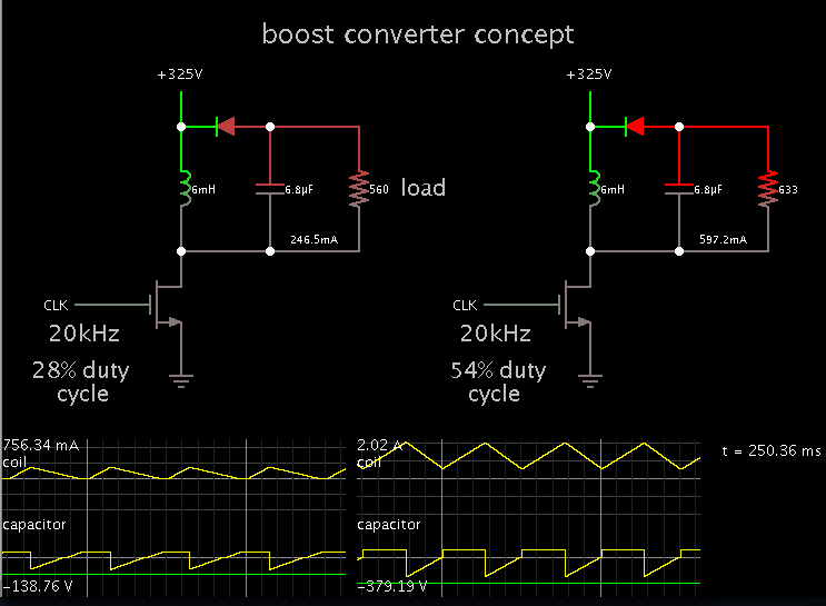
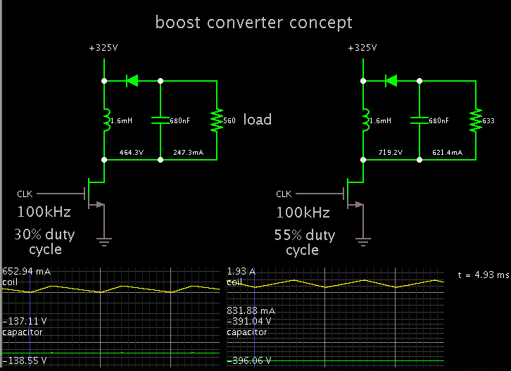
I would like to convert a voltage of 230VAC in a variable voltage between 140VDC and 380VDC (0.6A max.)
I assume 230VAC to a bridge (with capacitor) that comes into a DC voltage of 325VDC. Then it goes in a buck delivers 140V output and everything is in a boost assembly 140VDC variable (at a current of 0.25A) 380 VDC (at a current of 0.6A).


Is this feasible with these simple editing Buck / Boost?

How to drive the gate of the mosfet? (VG input is 325V ...).
 

Yes, you would obtain 325 VDC as you describe. However you can use a single buck-boost converter to step the 325 VDC up or down.

You select your output voltage by varying the duty cycle.
 

You can use an N-mos, and bias it normally. The converter goes in the high side, close to supply +.

To illustrate the concept of a buckboost converter (one putting out 140V, the other 380V):


380*0.6 = 228W, ..I would do an LLC converter as you can get the fet drivers on integrated control chip....I wouldn't do a split section bobbin, but just do a tight coupled trafo , and a "separate" external "leakage inductor"
There isa good fairchilsemi.com app note...AN4151 or something similar
https://www.fairchildsemi.com/an/AN/AN-4151.pdf
otherwise, do a 2 tran forward.
The LLC is best of you can put a boost pfc in front of it.

At 228W, if you don't have a pfc stage, then you will need a big cap bank after the mains rectifier, and your mains harmonics (3rd 5th etc) will be very high which is bad.
 

You can use an N-mos, and bias it normally. The converter goes in the high side, close to supply +.

To illustrate the concept of a buckboost converter (one putting out 140V, the other 380V):


Thanks. I'll try this tomorrow.

I'll try to change the switching frequency (100KHz at least see 500KHz) to reduce the value of the inductance.
For the N-channel mosfet, I just need to be careful VDS maximum (about 600 volts) and low RDSon.
The filter capacitor is calculated I guess (you set a default value?).


If I do not succeed I will look to the SEPIC configuration.
 

right, I see, floating load, yes that's a very good way.
Your fet will need rating to more than 600v as you know.
At 500khz, you will get massive switching losses in that fet.
So you do opto feedback?


SEPIC notes:
Remember sepic cap voltage need be greater than vin....so that's a big cap......or several in series. Remember with sepic and uncoupled inductos.....calculate the L-L-C resonant freq...then you do rc snub across sepic cap.
Rsnub = SQRT((L+L)/C), then Csnub = calc'd to be 1/(2.pi.Rsnub.Fres)
Also, remember current mode sepic above 50% duty need slope comp.....unless you do constant off time converter.
Make sure that your crossover frequency is either 3x greater than , or 3x less than, the L-L-C ringing frequency.
Make sure also that delta V on the sepic cap is no more than 5% of its steady state voltage.
Also beware start-up overshoot on sepic cap voltage.
 

Thanks. I'll try this tomorrow.

I'll try to change the switching frequency (100KHz at least see 500KHz) to reduce the value of the inductance.

Yes, for 100 kHz you can use a 1.6 mH coil, and capacitor .68 uF.

For the N-channel mosfet, I just need to be careful VDS maximum (about 600 volts) and low RDSon.

Notice the mosfet is exposed to more than 700 V (during switch-Off).

During switch-On it conducts about 1.4 A average, however it has only 1 or 2 volts applied to it during that time.

The filter capacitor is calculated I guess (you set a default value?).

I experimented with values until I got one or 2 percent ripple.

It absorbs pulses of more than 600 mA, which may or may not be too much for a physically small capacitor.


Status
Not open for further replies.

Similar threads

Part and Inventory Search

Welcome to EDABoard.com

Sponsor

Back
Top