Continue to Site

Welcome to EDAboard.com

Welcome to our site! EDAboard.com is an international Electronics Discussion Forum focused on EDA software, circuits, schematics, books, theory, papers, asic, pld, 8051, DSP, Network, RF, Analog Design, PCB, Service Manuals... and a whole lot more! To participate you need to register. Registration is free. Click here to register now.

Designing a Switch Mode Power Supply DC to DC

Status
Not open for further replies.

Latu Posi

Newbie level 4
Newbie level 4
Joined
Oct 1, 2013
Messages
6
Helped
0
Reputation
0
Reaction score
0
Trophy points
1
Visit site
Activity points
36
I am trying to design a +-15v switching regulator supplied from a 12v battery and the output current must be at least 1A. Is anyone please help me finding appropriate components and:roll a kind of switch to be used ?
 

1.

Since you want a bipolar supply, it is practical to chop the +12V through an H-bridge, which will produce AC square waves (roughly).

Then send the AC to a step-up transformer, with a center tap.

The trick will be to find the right transformer.

2.

As an alternative you could use:

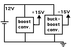
(a) a boost converter to step up +12 to +15
(b) a buck-boost converter to turn +12 into -15.

Both of these would share a common zero ground with your 12V battery ground terminal.
 

What do you think is possible and easy for me to design using the first option but i don't know what type of transformer to be used, but for the second option how can i combine the boost and buck boost do you have any sample of that, plse appreciate your help......cant figure it out this project...
 

The boost converter steps up the supply.

The buck-boost inverts the supply polarity, as well as stepping up its amplitude.

Each would be an independent supply, driven from the same 12V battery.

Here is a simple block diagram. It shows how they would be wired, including common zero ground.

9054258600_1380773454.gif
 

Honestly, i am in basic knowledge about Power Electronic and i don't know about all these things, i appreciate the big help..so i tried to figure it out the components to be used,the right switch and so on, so if you have more help about these project right components and all those stuff then the i am very appreciated..

thanks very much and *** bless !!
 

Please is there a switch regulator to replace the IC 7805 functionality regarding my project!!
 

The 7805 regulator is easy to use because it puts resistance in the path of the incoming supply V, to reduce it.

However it is more difficult to increase the voltage. That requires more components. More know-how. More soldering. More adjustments. Possibly burning out a component or two.

It will be a learning process.

To do it an easier way, you will need to purchase ready-made converters. 12V to +15V, and 12V to -15V.

Each would need to be rated for your spec of 1A max.
Total drain from your 12V battery will be between 2 and 3 A.
 

As i said it before i am new in this course, as some of the helpers say it better to do more research on this topic...but anyways thanks very much to you and everyone you sharing their experiences and advices regarding my project...
 

Status
Not open for further replies.

Part and Inventory Search

Welcome to EDABoard.com

Sponsor

Back
Top