Continue to Site

Welcome to EDAboard.com

Welcome to our site! EDAboard.com is an international Electronics Discussion Forum focused on EDA software, circuits, schematics, books, theory, papers, asic, pld, 8051, DSP, Network, RF, Analog Design, PCB, Service Manuals... and a whole lot more! To participate you need to register. Registration is free. Click here to register now.

Designing a Boost converter..

Status
Not open for further replies.

Jay R

Newbie level 5
Joined
Jan 13, 2014
Messages
8
Helped
0
Reputation
0
Reaction score
0
Trophy points
1
Activity points
52
hi,
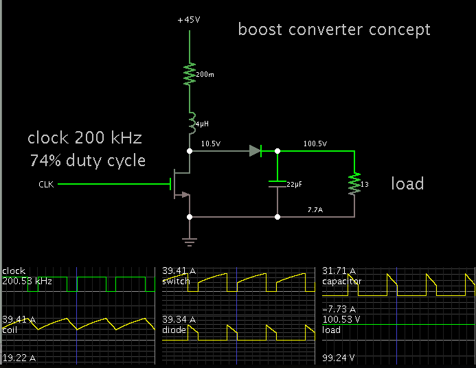
I need to design and build a boost circuit for my school project and all I am given is the following specifications:
Voltage in is 45v to 75v
voltage out is 100v (eventually they want 150v)
the power is 800w
and the current is 8amps
the switching frequency is 200 kHz
and the efficiency is >=90 %

any help with this would be greately appreciated.

- - - Updated - - -

sorry the output current is 8 amps
 

Have you examined schematics of boost converters?

Have you seen calculator websites which assist in selecting component values?

Did the assignment specify a particular IC to control it?

As a hint: the coil's Henry value must allow current to rise to 30 A during switch-On, then fall to zero during switch-Off. (Figures are approximate.)
 
  • Like
Reactions: Jay R

    Jay R

    Points: 2
    Helpful Answer Positive Rating
I have been looking at schematics of boost converters have not seen calculator websites to assist yet and no specific IC to control it. Im a beginner at all this and really am unsure how to achieve the desired output
 

You can explore the rudimentary concepts by clicking the following thread. See my post #6.

https://www.edaboard.com/threads/268178/

It contains a link to an interactive animated boost converter.

It will open the site www.falstad.com/circuit, load my schematic into the simulator, and run it on your computer. (Click Allow when it asks permission to load the Java applet.)

The converter has different specs than yours. You can adjust values by right-clicking (or with Mac use ctrl-click) on a component, and select Edit.
 
  • Like
Reactions: Jay R

    Jay R

    Points: 2
    Helpful Answer Positive Rating
Thank you I am trying to open this simulation its not working correctly but I think I messed up will continue to try
 

Hi Jay R, I would like to recommend you a book, called Power Supply Cookbook. It's not a really book, is something like a technical reference manual with all the theory very well explained and design examples. I don't know your ability to buy components but this ebook also contains specific component values, for instance for inductors.
 
  • Like
Reactions: Jay R

    Jay R

    Points: 2
    Helpful Answer Positive Rating
Thank you I am trying to open this simulation its not working correctly but I think I messed up will continue to try

If you need to reload the original schematic, you must close all falstad.com windows. Then click my link again.

Or, this is how to save a circuit:

Select File >> Export.
A window appears containing text.
Copy the text and paste it into a word processor.

It would be easy for me to fill in the values for the coil and capacitor, but those are only a little step in view of the work you're likely to put into this power supply.
 
  • Like
Reactions: Jay R

    Jay R

    Points: 2
    Helpful Answer Positive Rating
It would also be worth looking at creepage and clearance information.

**broken link removed**
 
  • Like
Reactions: Jay R

    Jay R

    Points: 2
    Helpful Answer Positive Rating
I was just updated with a circuit design and that we are allowed to use an ic.. anyone know of any ic that can handle 800 w and voltage input of 45 to 75 volts and cause the circuit to output 100volts?

Thank you for your responses
 

Hi Jay R., you said, you need an IC of 800W!!!. I don't think that something like that exists, or at least I've never seen nothing like this before. In a previous post I suggested you a book, did you saw it?. For your design you should use an inductor, which maybe must be capable of handling a current of at least 8A, maybe more. Please, take a chance to see the ebook. I've sent you a link to it, ready for download. This ebook is very good, I've learned too much from it. Yosmany.
 

well I guess I worded it incorrectly the overall circuit out put must be 800 w and 8amps with an output voltage of 100v. the input to the circuit will be from 45 v to 75 volts and must result in the specified output. I will be looking at the book thank you
 

Just to help progress along in the right direction...

To get 800W out, you must put in that amount of watts, plus some.

This simulation shows a simple boost converter. The coil is the heart of the action. As you can see the coil is 4 uH, a suitable value to operate at 200 kHz. It must carry an average of 30 A at 45 V, if you want 100 V at 8 A.


I added a 0.2 ohm resistor to represent parasitic losses in the converter, 100 W or so.

A lot of power is also lost during switch-On. For this reason you may decide it is more efficient to use a transformer instead of a boost converter.
 
  • Like
Reactions: Jay R

    Jay R

    Points: 2
    Helpful Answer Positive Rating
Is that using your simulation program BradtheRad?
 

Is that using your simulation program BradtheRad?

The schematic itself was drawn by me using Falstad's simulator. I made it to be an aid for getting a grasp of basic concepts of the boost converter.

I also have my own animated interactive simulator which I programmed over the years. I have posted several Youtube videos under the name 'patientbrad'. Someday I hope to develop my simulator so it works well enough to distribute.

Here is a link to my video which shows basic principles of buck/ boost/ buckboost converters.

www.youtube.com/watch?v=FT_sLF5Etm4
 

Thank you for all your help the problem is now solved. I appreciate it
 

New part to this project. Remove the function generator and replace with a PWM controller to keep the output voltage steady regardless of the input voltage and still opperate at a 200kHz switching frequency and advice?
 

Status
Not open for further replies.

Similar threads

Part and Inventory Search

Welcome to EDABoard.com

Sponsor

Back
Top