dtothec
Newbie level 3

- Joined
- Feb 17, 2014
- Messages
- 3
- Helped
- 0
- Reputation
- 0
- Reaction score
- 0
- Trophy points
- 1
- Activity points
- 42
I hope this is in the right place and apologize if it isn't.
Not too long ago I posted a thread about a Cuk converter that I was tasked with designing. Currently I have hit a snag yet again and hope that its as simple a fix as the last problem I had.
I am using an LM5025 as a PWM to help control the Cuk converter. I found a post online that showed a circuit schematic using only the LM5025. I built that circuit in PSpice and simulated it. Then I copied my Cuk converter over into the design and simulated it again. Both circuits can run just fine on their own, but when I connect the two I get problems. The voltage source connected to the gate of my MOSFET is a Vpulse with peak-to-peak voltage of 5V. I have also made a voltage divider at OUT_A of the LM5025 to get the voltage there to around 3.7V. I set the transient analysis as: Run time = 1ms, save data after = 0.1ms, max step size = 0.1ms.
When I connect the two circuits together I make a connection from the gate of the MOSFET (I remove the Vpulse) to the voltage divider. However the simulation never runs and always gives an error that says "ERROR(ORPSIM-15138): Convergence problem in transient analysis at Time= 208.7E-09". I'm unsure of what that means. I also believe that there might not be enough/too much current running through the MOSFET when the connection is made. If anyone could give any advise or point me in the right direction I would be very grateful.
Thank you for your time,
dtothec
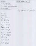
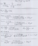
I have attached pictures of both the Cuk converter and the LM5025 circuit, and the calculations I used to design the converter.


