Continue to Site

Welcome to EDAboard.com

Welcome to our site! EDAboard.com is an international Electronics Discussion Forum focused on EDA software, circuits, schematics, books, theory, papers, asic, pld, 8051, DSP, Network, RF, Analog Design, PCB, Service Manuals... and a whole lot more! To participate you need to register. Registration is free. Click here to register now.

Design gate driver for Igbt

Status
Not open for further replies.

m.heshmat

Newbie level 5
Joined
Feb 1, 2013
Messages
10
Helped
0
Reputation
0
Reaction score
0
Trophy points
1,281
Activity points
1,359
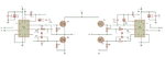
i using microcontroller pic16f877A to generate pwm , and i want to design the gate driver for igbt ( HGT1Y40N60C3D ) using transistor tip122 , what steps can i do ??
 

thanks for your help ( Eectro nS ) , i already using Ir2110 but the lo ( low side output drive ) is seem to be very small signal , however the HO ( hign side output is 12V ) , and i don't know what is the problem , i replace the IR2110 three times

can i use two IR2110 and use the HO output to drive the low side IGBT and the High side IGBT ????
 

Please post your schematic, I've use the IR devices before, and they are very reliable.
Did you purchase the IRF 2110 from a reliable vendor?
There are countless posts of individuals purchasing components in the gray market, with terrible results.
 

thanks for your help ( Eectro nS ) , i already using Ir2110 but the lo ( low side output drive ) is seem to be very small signal , however the HO ( hign side output is 12V ) , and i don't know what is the problem , i replace the IR2110 three times

can i use two IR2110 and use the HO output to drive the low side IGBT and the High side IGBT ????

IR2110 is one of the best gate driver IC.

voltage difference will be tre for the low side driver and high side driver due to bootstrap voltage.
no need to go with two IR2110 with it's HO. pointless.

what's the voltage level u r getting in LO & HO? what abt load voltage waveform when u give proper switching pulse considering dead time.

- - - Updated - - -

ref this thread for gate driver circuit: https://www.edaboard.com/threads/75021/
 

Give the schematics plz...there are lots of good threads on IR2110 in edaboard...just go for it
 

thanks for your help ( Eectro nS ) , i already using Ir2110 but the lo ( low side output drive ) is seem to be very small signal , however the HO ( hign side output is 12V ) , and i don't know what is the problem , i replace the IR2110 three times

can i use two IR2110 and use the HO output to drive the low side IGBT and the High side IGBT ????

as the guys pointed out the gate driver might be not good , due to storage and handling issues by the supplier , if you buy if from digikey for example notice how the packing is very special ( regarding humidity and ESD ....)

another problem might be your circuit , so post your schematic with values of capacitors , resistors ....
by the way 1 IR2110 can drive your IGBT easily ( it is a 2A driver ) . also check out HCPL-3120 opto isolated driver , shane (scolton.blogspot.com) has done project on these , he post schematics , maybe that would help

take care man and good luck
 

the problem is that the output of IR2110 as follow
HO is 12V squre wave ( good signal )
LO is 12V but constant dc voltage not squre wave however the input (Li) is squre wave
what is the problem ??


can any one help me to design gate drive using transistor 2N2222 ??
 

Attachments

  • IR2110 - 3.png
    IR2110 - 3.png
    91.1 KB · Views: 232

LO is 12V but constant dc voltage not squre wave however the input (Li) is squre wave
what is the problem ??
Doesn't sound plausible at all.
 

Agree that it doesn't sound plausible.
Usually the high side is the one that gives problems, since the charge pump must be working properly........ but the low side? That should give an output waveform even without the Mosfets connected.
 

It might happen if VCC to COM voltage is below UVLO threshold.

P.S.: Sorry, complete nonsense. The report was about high output voltage. UVLO would force low voltage. So it's either active input signal, defective driver IC or missing COM connection.
 
Last edited:

HO is 12V squre wave ( good signal )
LO is 12V but constant dc voltage not squre wave however the input (Li) is squre wave
what is the problem ??

If lower side switch doesn't get triggered then how come HO can give pulse o/p. with charging boost charge capacitor high side pulse will not come.

have u tried after changing IR2110? still is it coming like that?
 

from my standpoint IR2109 driver ic is more suitable.

but in this time i do not check it in practice )
 

Looks like that scheme with ir2109 works, certainly it is necessary to correct program to take away spikes.
 

Attachments

  • m8.zip
    4 KB · Views: 67

amended version of the program.
in this moment work of converter is checked only with 4 Ohm load at 14V supply voltage
 

Attachments

  • c&hex.zip
    4 KB · Views: 57

Status
Not open for further replies.

Similar threads

Part and Inventory Search

Welcome to EDABoard.com

Sponsor

Back
Top