Continue to Site

Welcome to EDAboard.com

Welcome to our site! EDAboard.com is an international Electronics Discussion Forum focused on EDA software, circuits, schematics, books, theory, papers, asic, pld, 8051, DSP, Network, RF, Analog Design, PCB, Service Manuals... and a whole lot more! To participate you need to register. Registration is free. Click here to register now.

Delay circuit for Negative voltage

Status
Not open for further replies.

h3ndrix

Newbie level 6
Joined
Sep 17, 2013
Messages
13
Helped
0
Reputation
0
Reaction score
0
Trophy points
1,281
Activity points
1,416
Hello,
I need help on something that I cant quite get my head around. I am using a psu with +15v and -15v output for a galvo head. For the specific head, I need to add a delay circuit that delays both power lines for a sec. I found a lot of positive voltage delay circuits but dont have a clue what a negative voltage delay circuit would look like. Any pointers would be appreciated. Thank you.
 

Hi,

to me it´s not clear what you need. Please draw as sketch with voltages and timing.
Where do the 15V come from?

1s from which point of time?

Klaus
 

Hello Klaus,

Maybe I wasnt clear enough. I have attached a basic drawing of what the system is like. On the right is the PSU that I was talking about. This PSU powers the galvo control and it also has a pass-thru to the galvo head, which also receives its power from the same PSU. The control needs to power up before the galvo head that's why I need to delay the power that passes through the controller to the galvo. The delay circuit needs to be in between the controller and the galvo. Is that understandable? Thanks.

EXAMPLE.jpg
 

Are this an issue to the controller device (i.e. advice on how to set it up) - or to use some external circuit to solve this?

If latter, then you could use an RC circuit, a schmitt trigger and a relay with two independent contacts (DPDT relay).
 

Below is the LTspice simulation of a four transistor circuit that controls both the plus and minus supply voltage with one control input:
The plus switch is an NPN grounded-emitter transistor (trough Q3's emitter base) driving a PNP switch.
The minus switch is a grounded-base transistor driven by the base-emitter current of Q1, driving an NPN switch.
Can the controller provide the delay signal or do you need a circuit to generate that?

1636076317738.png
 
Last edited:

Thanks all,

Unfortunately the controller cant control the delay because the outputs are used up.

Crutschow, is it possible that this circuit will also act as a soft start?

Thanks.
 

Hi
Unfortunately the controller cant control the delay because the outputs are used up.

Crutschow, is it possible that this circuit will also act as a soft start?
..piece by piece information.
That's why I wrote (in my first post)
Please draw as sketch with voltages and timing.
We don't know
* what's the aim of the soft start(limiting current, limiting voltage rise rate, to achieve symmetricity..)
* timing accuracy,
* drawn current,
* max dropout voltage,
* whether the load is ohmic or capacitive or inductive, ...
* psu type (link to datasheet)
* galvo type (link to datasheet)
.. which of the above itmes is more important for you, which are less...

The faster and the more informations you give ... the faster you will get a suitable solution

Btw: what's the key problem when the voltage is applied immediately?
It's not very common that a "device with communication" needs a dedicated timing for powering up with respect to the other communication partner. Maybe there is a much simpler solution....

Klaus
 
To address the thread title here is a simple method to delay negative supply to load.
RC curve drives a sziklai pair. Values adjusted to achieve 1 sec delay. Using NPN as the final transistor allows the load to be placed closest to 0V ground.
This method is not necessarily better than the ones already suggested.

delay 1 sec on power-up then 1A to load PNP NPN neg V supply.png
 

OK, I will try to give more information but, as I said, I am no expert and I am going by what the literature and from what the controller manufacturer states.

The controller is a Halaser E1803D that works with USB power (some functions) and the PSU that also powers the Galvo.
The Galvo is a Scanlab Hurryscan 10, it works with a PSU (that also powers the E1803D) that has +/- 15V lines.
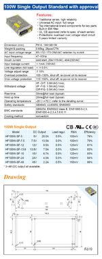
The PSU in question is a Heng Fu HF100W-D-L, which is a PSU that takes mains power and outputs +/-15V.
I have attached all the documents relating to this equipment.

It is probably obvious but, none of this equipment is certified to work with each other. However, as this is a University R&D project, they were gathered from different places for bargain prices, and as the researcher (professor) in the project, I am trying to bring them together. And, I have, I can now do marking and they all work but, there is a problem and I need to fix it and will explain it in detail.

Here is what happens when I turn on the power. The E1803D powers up fine, the Galvo makes gurgling sounds and then goes quiet for about 10-20 seconds and then one of the motors loses holding torque and it is possible to hear a very high-frequency hum. While this happens, it is not possible to send any data to the Galvo, it does not accept any kind of commands. I tried this several times and stopped trying to prevent some kind of damage to the Galvo control electronics.

The connections were given in my previous post. The E1803D, as told to me by the manufacturer, does not send any comm data to the Galvo until a marking operation is called. So, this problem is happening from the power delivery. When I first posted to the forum, I had not received the manual for the Galvo from Scanlab, they took some time to respond. Now, I have the manual and it clearly states that a soft-start PSU should be used to power the Galvo. What I was thinking was along those lines and the reason for posting was to delay the output from the PSU until it settled. However, I also figured that a soft-start circuit with a Mosfet may also be used in front of the PSU for a gradual increase of current instead of using a delay circuit on the output (?).

The way I got it to work, which is also the reason that I asked for a delay circuit, is that I disconnected the Galvo power before switching on the power for the system. About a second after I switched on the power, I connected the power to the Galvo and everything started to work fine. However, the Galvo manual also states that the power connection should not be played with, as expected. I do not want to constantly connect power in this manner as I might destroy the Galvo electronics in some manner.

I hope this explains it better. However, I do not know the answers to these questions Klaus, unfortunately, my knowledge in electronics is limited. I can't answer,
* timing accuracy,
* max dropout voltage,

But, I can say that the max. current that the Galvo is supposed to draw is 3A but, that's if both motors stall at the same time. It usually draws about 500mA-1A when both are working depending on their paths.

I don't know if I should use a soft starter in front of the PSU that can ramp up to the specified voltage/current or use something as suggested by the valuable posters on the outputs.

Thanks.
 

Attachments

  • e1803_manual.pdf
    1.2 MB · Views: 172
  • hurrySCAN10_dig_1064nm_254mm_112466_e.pdf
    472.4 KB · Views: 125
  • PSU.jpg
    PSU.jpg
    379.5 KB · Views: 77

Below is the LTspice simulation of my circuit with a soft-start function added, and MOSFET outputs to provide the 3A maximum current.
C1 and C2 generate a MIller effect integrator function to give about a 1 second linear ramp of the output voltages.
I think with that you likely don't also need a delay.

The diodes and resistors R7 and R8 are to help discharge the capacitors and reduce the turn-off time to be similar to the turn-on time.

The N and P MOSFETs can be just about any with at least a 30V rating, and an on-resistance ≤50mΩ.
The should also have similar Vgs(th) values.

1636267298308.png
 

Hi

To me it sounds as if there is an over current situation.
I recommend to de install all your switching and delay circuit. Install voltage and current measurement to trace them during start up. Check for oscillation, ringing, hickup..

I agree that -especially for capacitive loads - there is a benefit in limited voltage rise rate. Anything about 1...10V/ms.

Extremely slow rise rate is a quite untypical requirement for a power supply or a device.

Better remove the cause than curing the symptom.

Klaus
 

I agree that -especially for capacitive loads - there is a benefit in limited voltage rise rate. Anything about 1...10V/ms.

Extremely slow rise rate is a quite untypical requirement for a power supply or a device.

Yes, a faster power rise-time will likely also work.
In my circuit, if you reduce the value of C2 and C3 to 1µF for example, the power rise-time will be about 12ms.
 

+/-15V 2A
--- Updated ---

Below is the LTspice simulation of my circuit with a soft-start function added, and MOSFET outputs to provide the 3A maximum current.
C1 and C2 generate a MIller effect integrator function to give about a 1 second linear ramp of the output voltages.
I think with that you likely don't also need a delay.

The diodes and resistors R7 and R8 are to help discharge the capacitors and reduce the turn-off time to be similar to the turn-on time.

The N and P MOSFETs can be just about any with at least a 30V rating, and an on-resistance ≤50mΩ.
The should also have similar Vgs(th) values.

View attachment 172746
Add 1mF to each output and show temp rise on FETs

since the motors can take 10x 2A on rapid start, I would expect a motor model to have a DCR of 0.75 Ohms then rise to 7.5 ohms so dV/dt must factor a surge of heat on both output stages.. so a switching regulator CC start would be best for soft start using PWM limited by current.
 
Last edited:

Why 1mF?
The energy dissipated in the MOSFETs from charging a 1mF capacitor to 15V is 1/2 CV² or 112mJ, which will not cause a noticeable amount of heating.
I was later think about a motor with 0.75 DCR and then simulated it with 12W peak power for a 5s ramp with a suitable friction coefficient and torque to load with 2A. Yes C is irrelevant .

Best case current limit is at a matched source impedance on start where 30Vx2A = 60W is limited at half power point. But impedance is non-linear so 1/4 power loss or 15W. So PSU does not OCP shutdown. (assuming that exists)

now what heatsink is needed and RdsOn is irrelevant during startup.

what would you recommend now?
 
Last edited:

Status
Not open for further replies.

Part and Inventory Search

Welcome to EDABoard.com

Sponsor

Back
Top