Continue to Site

Welcome to EDAboard.com

Welcome to our site! EDAboard.com is an international Electronics Discussion Forum focused on EDA software, circuits, schematics, books, theory, papers, asic, pld, 8051, DSP, Network, RF, Analog Design, PCB, Service Manuals... and a whole lot more! To participate you need to register. Registration is free. Click here to register now.

Decouplig inductor choice?

Status
Not open for further replies.

carpenter

Full Member level 6
Joined
Jul 25, 2012
Messages
353
Helped
22
Reputation
44
Reaction score
24
Trophy points
1,298
Activity points
4,467
For example in coaxial line is high power AC 15MHz 200Vrms and we need add in this line small DC current 10mA,
I thing we use inductor with high impedance for AC and small for DC
For exemple NLC453232T-560K-PF
In graph on page 7 I choice inductor with max real induktance on 15MHz 560k 56uH with 80uH on 15MHz
In next step I look on page 9 impedance on 15MHz for 560k is any about 50k Ohm and 2,2 Ohm for DC.

Is it the right choice?
The coil has SRF 11MHz will not this problem?
How is it with voltage resistance?

Thanks
 

You need to post a schematic of exactly what you are talking about - for me, what you want to do is not clear. If you are using the inductor path as a DC power feed, then you want as high of inductance (at the SRF) as you can, given the restraints of size and current carrying capacity. To put an inductor with a SRF below your operating freq in that situation would be a disaster, because above the SRF, the inductor will look like a capacitor.
 

To put an inductor with a SRF below your operating freq in that situation would be a disaster, because above the SRF, the inductor will look like a capacitor.

It's no bad idea as such to use a choke near (or slightly above) the SRF because the impedance is maximal. "Look like a capacitor" is true, however if the capacitance is only about 2 pF, this doesn't mean much.

I see a problem that the shown devices aren't specified for high RF voltage. It's not obvious if the dielectric strength is suited for voltages > 100 Vac and there's a risk that the ferrite losses cause excessive core heating.
 

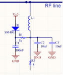
OK her is schematics.

It is very simple.

On RF line is any high power for example 15MHz 200W to 50 Ohm.
Over L1 is on this line injected small DC current from R1
Over R2 is detected voltage on L1/R1 if is all OK and DC current go to load on RF line is voltage small
if load is disconnected DC current not go over RF line and voltage is 5V it is all.

In THT version I use 220uH axial inductor any as this (wire coil on ferrite rod) and all works OK, but for final realisation I nedd any small SMD solution.

Choke.png
 
Last edited:

It's no bad idea as such to use a choke near (or slightly above) the SRF because the impedance is maximal. "Look like a capacitor" is true, however if the capacitance is only about 2 pF, this doesn't mean much.

The capacitor in the inductor is in series, so at resonance, the impedance of the inductor is equal to the coil resistance. Not to good, if you are trying to block RF. This is why I recommended to use as large of an inductor as feasible.
 

The capacitor in the inductor is in series, so at resonance, the impedance of the inductor is equal to the coil resistance. Not to good, if you are trying to block RF.

No it's in parallel, and the impedance is maximum at the inductor SRF, as any inductor datasheet with impedance curves clarifies.
 

I will return the discussion to the technical relization.
If I look on mouser.com , and offer SMD coils.
Only a few types describe the impedance at frequencies above 10MHz.

Size 1210 NLCV32T
Size 1210 NLCV-EFD
Size 1210 NLCV32-EF
Size 1210 NLFV32-EF
Size 1812 NLC453232

Anywhere I have not comprehended what the voltage resistance is and what strain they can withstand in the long term?
From a practical point of view, what is the working frequency position relative to the SRF?
Or otherwise, which coil would you use, or 2 in a row
 

No it's in parallel, and the impedance is maximum at the inductor SRF, as any inductor datasheet with impedance curves clarifies.

Yeah, you're correct... I was thinking of a capacitor with its two series inductors. Looking at an inductor on a Smith chart, the S11 is (0 - 0j) at SRF, which means that the inductor appears as a very large real impedance at resonance.

As for returning to the technical realization, I have no idea what you mean in your questions. You previously stated that your current thru the inductor is 10mA, you know what freq you are operating at, so what is the problem with selecting an inductor?
 

what is the problem with selecting an inductor?
For example.
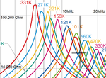
On pic is detail from IMPEDANCE FREQUENCY CHARACTERISTICS GRAPH NLC453232
On coil with impedance over cross point are applicable.

Blue 56uH left on SRF
Red 68uH right on SRF
Green 82uH near SRF

Graph is for 25C my device have working temperature up to 60C.
I do not know in which direction the chart moves with the rising temperature.
That's why I do not know which one to choose from.

Voltage drop on the coil (AC voltage) will be 200V, the coil has a lot of thread very thin enameled wire.
On thit may occur short circuitsd and the manufacturer in the datasheet does not specify max working voltages voltahe drop on coil.

coil.png
 

200V is not enough to break down the insulation of the wire. Your only concerns are the current carrying capability and what value of impedance that you want. If your system is 50Ω, your impedance should be at least 10X that, or 500Ω. More is better, but that means thinner wire, more turns and lower current capability. If you choose air (or alumina) core devices, you shouldn't have to worry about temperature drift.
 

Thanks all.
I ordered a couple NLCV32T-101K-EF
We will try,we we wil see.
Thank you once again
 

Status
Not open for further replies.

Similar threads

Part and Inventory Search

Welcome to EDABoard.com

Sponsor

Back
Top