Continue to Site

Welcome to EDAboard.com

Welcome to our site! EDAboard.com is an international Electronics Discussion Forum focused on EDA software, circuits, schematics, books, theory, papers, asic, pld, 8051, DSP, Network, RF, Analog Design, PCB, Service Manuals... and a whole lot more! To participate you need to register. Registration is free. Click here to register now.

De-linearizing the output of a Hall sensor

Status
Not open for further replies.

Altair2

Newbie level 4
Joined
Jul 1, 2018
Messages
7
Helped
0
Reputation
0
Reaction score
0
Trophy points
1
Activity points
83
Hi everyone,
I have an e-bike on which the throttle handle is based on a Hall effect sensor, with an output that varies between 0.8V-4.0V depending on rotation of the handle.
I would like to have a more logarithmic output curve from the sensor, instead of the roughly linear curve.
I have designed a circuit that takes advantage of the non-linearity of a PN junction to pull down my curve, but this type of circuit is not temperature-stable, and also not variable in its effect, meaning that I cannot adjust my curve fron linear to logarithmic without modifying the circuit.

So the reason of my visit here is to gather ideas as to how I could accomplish such a thing.
A few of the ways to attain that goal could be for example, go digitally with a read-out table, and then use a balance pot to smoothly select between both extremes.
Or use a log amplifier...
Or use a FET as a variable resistor to pull the output voltage down when it is low, let it rise when it is higher, everything being just a balance of resistors affecting the impedance of the signal line. Or use a VCA chip instead of the FET.
I would like to find a simple solution, I don't need precision, just that the maximum and the minimum voltages be the same as what comes out of the Hall sensor. And that it be adjustable with a single pot.

What do you think? Am I looking for the imposible?
Maybe a simpler solution would be to change the Hall throttle to a resistive potentiometer-based one, and add a pot between wiper and ground, which allows a nice (and adjustable) pulling down of the curve.;-)
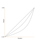
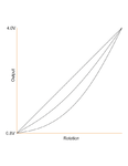
Hall throttle.gif
 

You can buy log-amps that do what you want, only accurate.

Not sure why you want a logarithmic throttle response, in
my experience (automotive) throttle body cable cams are
often more like exponential. Nothing, little bit, little bit more,
B-wah!
 

Thanks, In fact, I'm not sure if I should have used the word exponential instead of logarithmic...
The bike is quite powerful, for off-road only, so I want to tame the low-throttle region so it is a bit more "civilized".
Then, whith wide open throttle, it's a beast.
I have modified my pic of the curves (CAD-drawn), to better represent what I'm after.

Hall throttle.gif
 

There is an endless variety of arrangements of resistors you can add across a potentiometer, to change its curve. You need to start with the right value pot, and find the right value resistor or resistors. To calculate the proper values will require countless experiments.

The curve you want may only be available from a logarithmic pot.

I have designed a circuit that takes advantage of the non-linearity of a PN junction to pull down my curve, but this type of circuit is not temperature-stable, and also not variable in its effect, meaning that I cannot adjust my curve fron linear to logarithmic without modifying the circuit.

You can spread heating effect by stringing several diodes in series. This also gives you an expanded range of response. Since one diode responds over a range of about 0.3 to 0.7V, you might try putting three in series so you get an expanded range of 0.9 tp 2.1V.

You can get various response curves by adding series or parallel resistors (potentiometers).

Or possibly use led's or zener diodes.
 

You might be able to simply modify the sensed element
(magnet?) so that its behavior suits you. Take apart an
eBay spare maybe, and see how the magnetic field is
varied by the twist; maybe just needs a little grinding
in the midsection.
 

Besides the option of modifying the primary sensor characteristic as mentioned by dick_freebird, there are methods to design temperature compensated non-linear function circuits. The basic building block is matched transistor (or diode) pair with an additional means to compensate for kT dependency. As an example, see below a log circuit from classical National AN-30.

logamp.PNG

Arbitrary non-linear characteristics can be either linear-piecewise approximated with diode networks or synthesized with differential pairs.

For the present problem, you would start with specifying the intended characteristic.
 

@ BradtheRad, the additional resistor on a pot would indeed be the easiest solution, but I would have to change the throttle to a resistive one, and they are $90, vs the Hall types at ~$15. Go figure...
@ dick_freebird, I've checked that option and it would not be easy, the magnet is a curved long piece and trying to modify it by grinding wouldn't change the progression of its magnetic field, I'm afraid.
@FvM, yes this is probably the obvious solution, but I would be way over my head trying to fine-tune such a design. My competence level doesn't go that high. :oops:
 

Hi,

I think the most fkexible solution may be a (8pin) microcontroller:
Input_voltage --> ADC --> digital processing (simple) --> PWM --> LPF

Klaus
 
  • Like
Reactions: asdf44

    asdf44

    Points: 2
    Helpful Answer Positive Rating
Thanks Klaus, I know nothing about DSP but I'll check that out for sure. It might be a very good option.
 

Yes I started typing to suggest a microcontroller before I noticed Klaus already did.

For this application I imagine 8-12 bits of ADC/DAC resolution and 10mS type latency is good enough and that's a peice of cake for a ~$1 micro.

Not only will digital be infinitely flexible but I believe it will be a cheaper/smaller solution as well with the (not insignificant) caveat that you'll need to write some minimal code and have a programming step in your manufacture.

I'd take a look at microchip. They have cheap parts with impressive capabilities including comparators and opamps that can be used as DAC output drivers/ADC input buffers. And they work pretty hard to make it easy for beginners.
 

Hi,

Digital signal processing often is just multiplying and adding.
In your case some compares may be necessary.
It's no rocket science.

Klaus
 
If dealing with the programming skill/stuffs is an issue for you, perhaps you would prefer choosing an analog solution as a small integrated circuit, such as the AD633 from Analog Devices (figure 13 from that datasheet seems like being what you need).
 
That analog multiplier is very interesting, but it needs a bipolar supply of 8V minimum. I have only 5V unipolar available.
I think I'll have a good look at DSP, even if I would have preferred having an analog solution, I'm an old guy of 64, so analog is in my blood...;-)
Thanks for the suggestions, guys!
 

Something that you could also do, along the lines that Klaus has suggested, is to have a lookup table which will convert the raw ADC counts from the digitized input to the transfer function of your choice.

You can calculate everything with an excel spreadsheet.
 
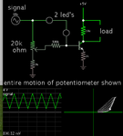
Simulation which yields the curves you want, by adjusting one potentiometer. It is based on the non-linear voltage drop of 2 led's. At low signal levels the NPN transistor is weakly biased. As signal level climbs, the led's conduct, increasing the slope of the output.The right-hand graph plots incoming signal versus load voltage.

My schematic has the load referenced to the positive supply wire. You'll probably want to install a second transistor PNP so that you can take output as referenced to 0V ground.

logarithmic curves output fm NPN 2 led's in bias tri wav 800-4000mV.png

The incoming signal is 0.8 to 4V. This suggests a 4-5 V supply is available.
 
I've never tried a simulator before, now I MUST have one!
Brad, I notice that the knee of the curves are all positioned towards the right. I had not tought about this before but, assuming that horizontal is the input and vertical is the output, it would be preferable that the knees be positioned close to the low-end of the input, effectively lowering the slope of the curve right when I'm just opening the throttle, and from then on, a faster progression to the top.
Also, the curves must always begin and end at the same exact points relative to the input. A couple of trimmers might be necessary because different throttles have small differences in their lowest and highest voltages.
I realize that I've just complicated your life, and everybody else's too! :-D
Maybe the best solution isn't linear after all...
Thinking about the lookup table schmitt trigger suggested.
 

So a micro solution could also use the internal flash to store the trim values for each throttle. This eliminates a part and may allow automation of the calibration process.

Here is an example of a part with 10-bit ADC/10-bit dac for $1. Also note that it has opamps, comparators, pwm outputs, a bandgap reference and configurable logic gates.

https://www.microchip.com/wwwproducts/en/PIC16F1764
 

Thanks asdf44, this everything-on-a-chip solution is interesting.
I wasn't planning this as a production item, rather just a one-off, but if I can make a good automated system that can adjust itself to the min and max voltages of any throttle, it could be sellable.
On power-up, the unit could wait for the user to open the throttle to the max for sampling the max voltage, and only then, become active.
This is getting more involved that what I was originally planning, and I already have plenty of "in process" projects...:grin:

You guys gave me much more options than what I was expecting, thank you so much!
 

Status
Not open for further replies.

Part and Inventory Search

Welcome to EDABoard.com

Sponsor

Back
Top