cupoftea
Advanced Member level 5
Hi,
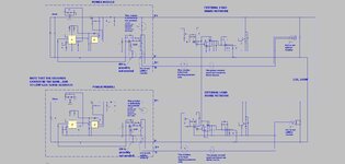
The attached shows a Buck converter with remote sense connections. The remote sense connection is also used , by adding a resistor, to do the Load sharing.
As can be seen, the full internal connection schematic of the remote sense lines are needed. Otherwise the Load share circuit cannot be done.
Why is is that no offTheShelf DCDC modules ever provide the details of the sense circuit connection inside the module…….the module simply cannot be reliably used if the internals are not known.
(LTspice and jpeg attached)