Continue to Site

Welcome to EDAboard.com

Welcome to our site! EDAboard.com is an international Electronics Discussion Forum focused on EDA software, circuits, schematics, books, theory, papers, asic, pld, 8051, DSP, Network, RF, Analog Design, PCB, Service Manuals... and a whole lot more! To participate you need to register. Registration is free. Click here to register now.

DC to DC converter for small wind turbine, requesting help...

Status
Not open for further replies.

BurnIt0017

Newbie level 6
Joined
Mar 13, 2010
Messages
14
Helped
0
Reputation
0
Reaction score
0
Trophy points
1,281
Location
earth
Activity points
1,404
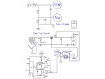
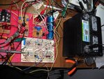
Hi, The circuit is working with a resistive load.

1. The mosfet source is connect to the high side of the load. The mosfet is a IRF510.

2. A IR2117 with bootstrap is being used and is referenced to Vs so the bootstrap capacitor voltage can be charged high enough to turn on the mosfet.

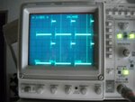
3. A 555 timer is used to control the IR2117 @ 10kHz with a 20 % duty cycle with a Vcc of 12 volts.

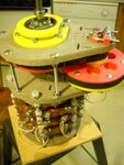
4. A permanent magnet alternator is used to supply Vin and can range from 0 to over 200 volts depending on the permanent magnet alternators RPM.

5. A bench power supply is used to supply power to the IC’s. This will be changed later.

The problem is :
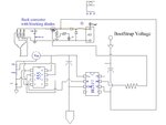
When the resistive load is replace with a 12 volt battery the circuit does not work.
I do not understand why the circuit will work for a resistive load and not with a 12 battery as a load. Any suggestion will be greatly appreciated.
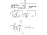
 

Attachments

  • TestcircuitConceptVccVdrDrawing.jpg
    TestcircuitConceptVccVdrDrawing.jpg
    53.2 KB · Views: 190
  • PMA.jpg
    PMA.jpg
    119.2 KB · Views: 114
  • a1.jpg
    a1.jpg
    127.8 KB · Views: 103

You are informing that the connection of the battery does not work.The switching pulses are greater than 17VDC??/Alternately , the series inductor needs to be loaded to generate a forward current ...However , inductor is blank within the B+ and the drain. during the OFF status of the MOSFET switch.
 

Hi, the video shows a resistive load, the circuit is only working with a resistive load. I would like to make the circuit work as a 12 volt battery charger. When I use a 12 volt battery for the load the mosfet does not turn on.

The bootstrap capacitor of the IR2117 is charged to 10 volts. Vs of the mosfet and the IR2117 are connected to plus 12 volts of the battery. The maximum voltage of the bootstrap capacitor can be +/- 20 volts, is that referenced to, ground or to Vs?? I do not know.

When I use a 12 battery as a load, what does the bootstrap capacitor have to be charged to and what do I use as reference? Thank you for any help received.
 

Why not put a resistive load to ground as well as the battery to collect charges ?//The resistor will act as load to the inductor for switching current stability ..
The battery +ve needs be provided with a diode for forward current into the plates and prevent VDC to be present to the MOSFET drain.when MOSFET is OFF.

Hi, I am not sure what you are suggesting, can you provide a circuit drawing? I think the reason why the N channel turns on when using just a resistive load is because Vs voltage is zero when the MosFet is off and Vg threshold is 4 volts. When the 12 battery is used as the load, the voltage at Vs is about 12 volts and the gate voltage is not high enough to turn on the gate. I am looking for away to increase the gate voltage to about 18 volts so the mosfet can turn on. I find the circuit very confusing. Comment welcome
 

I feel that when the MOSFET is on ,,,the source-drain channel is a shorting link with ON resistance .The input voltage 15V and output battery voltage of 15.8VDC cannot conduct in any direction at all.As such you may need to lower down the Drain voltage store marginally so that you can detect a pulse conduction for battery charging.The Back emf which generates the 15.5V can be reverse blocked by a FRR diode and mosfet drain terminated by a few milliamps to ground.This will help...
 

Hi, new test circuit based on information received and suggestions. Basically it is the same circuit as before with a blocking diode added at the plus battery terminal and a voltage pump for the bootstrap capacitor. Vg - Vs > Vthreshold , 20 - 12 = 8volts.
If it works the mosfet’s can be paralleled and the control circuits can be duplicated for increased current output.
 

Attachments

  • BatteryBuckConverterCircuit.JPG
    BatteryBuckConverterCircuit.JPG
    53.8 KB · Views: 171

Hi, I was able to find all the needed parts to make all the required connections to interface the circuit to a 12 volt battery. I am using to bench power supplies, one to power IC’s and the other for Vin.

I had just a LED and 22kohm resistor from the mosfet Vs to ground and the mosfet was turning on and off.

With a capacitor at the output of the circuit no current would flow into the battery. I removed the capacitor and I was able to measure 0.14 amps flowing into the battery.

I had attached a variable resistor to the 555 to be able to test different duty cycle, I adjusted the variable resistor to low and the 555 fried, so I have to purchase some replacements before I can continue testing. I will post more test results after I replace the 555.
 

Attachments

  • BlockingTestcircuitConceptDrawing.jpg
    BlockingTestcircuitConceptDrawing.jpg
    59.3 KB · Views: 119
  • protoAndBattery.jpg
    protoAndBattery.jpg
    129.6 KB · Views: 130
  • IR2117VsVs.jpg
    IR2117VsVs.jpg
    113.9 KB · Views: 78
  • outputCoilNoCap.jpg
    outputCoilNoCap.jpg
    114.4 KB · Views: 113
  • outputCoilWithCap.jpg
    outputCoilWithCap.jpg
    113.5 KB · Views: 109

Hi, the video shows a resistive load, the circuit is only working with a resistive load. I would like to make the circuit work as a 12 volt battery charger. When I use a 12 volt battery for the load the mosfet does not turn on.

The bootstrap capacitor of the IR2117 is charged to 10 volts. Vs of the mosfet and the IR2117 are connected to plus 12 volts of the battery. The maximum voltage of the bootstrap capacitor can be +/- 20 volts, is that referenced to, ground or to Vs?? I do not know.

When I use a 12 battery as a load, what does the bootstrap capacitor have to be charged to and what do I use as reference? Thank you for any help received.

How about your project sir?

I am developing similar circuit as yours. My buck circuit is able to work at resistive load and to charge battery 12V. However, I am facing issues like noises, voltage spike which damage microcontroller and mosfet driver.

May you have any suggestion. It will be appreciated.

Thank you
FOD3180_IRF840testCircuitConcept.JPG

Hi, this is the circuit I am using. I It is a 5 amp buck converter with a variable duty cycle, 10% to 50%. The control circuit is isolated with a opto isolated chip. The circuit will now work a resistive load and charge a 12 volt battery.
I am running 4 of the circuits in parallel for higher current charging. Max input voltage 400 dc, max output current 20 amps.
I hope you post a photo of your project. You should be able to use a similar chip to interface your micro.

FOURparallelFOD3180testCircuitConcept.jpg

this is the VAWT I am testing
2.jpg
 

BuckConverter&controller.jpg

Hi, this what my circuit looks like. You need a isolated power supply for the mosfet driver side. I hope this helps.
 

Hi Sir, Thank you for prompt reply.

Your schematic seems interesting. Now I am using IR2117 high side mosfet driver. But, sometimes Its broken suddenly. I guest because of noises which propagate inside it and disturb its fucntion.

I am considering to employ FOD3180 as high side driver but I have little bit confuse. I did not see the FOD3180 could be utilizes as high side mosfet driver at its datasheet.

Any suggestion? your reply really helpful.
 

Status
Not open for further replies.

Similar threads

Part and Inventory Search

Welcome to EDABoard.com

Sponsor

Back
Top