Continue to Site

Welcome to EDAboard.com

Welcome to our site! EDAboard.com is an international Electronics Discussion Forum focused on EDA software, circuits, schematics, books, theory, papers, asic, pld, 8051, DSP, Network, RF, Analog Design, PCB, Service Manuals... and a whole lot more! To participate you need to register. Registration is free. Click here to register now.

dc to dc converter circuit is needed please

Status
Not open for further replies.

Abdulhakim

Newbie level 5
Joined
Dec 11, 2014
Messages
8
Helped
0
Reputation
0
Reaction score
0
Trophy points
1
Activity points
50
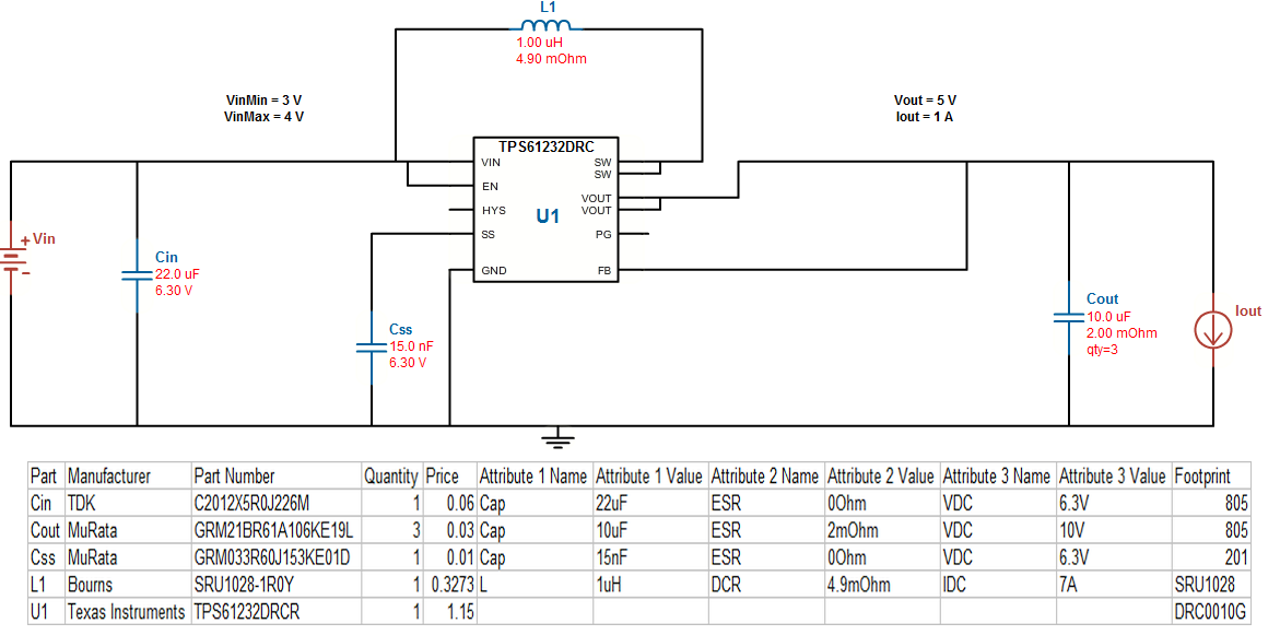
i want some to send me a 3.7v to 5v converter circuit diagram please
 
Last edited by a moderator:

voltage rating is not enough, u also need to provide the load current continuous, peak and average. For anything less than equal to 1A, u can use the boost converter IC from different manufacturer like NI, linear tech, analog devices etc. U can get the complete part selection from their respective websites.
For currents more than few amperes, usually a separate boost converter is used with MCU to control switching cycle. U can designs from google. microchip.com has several reference designs and application notes for boost, buck and flyback converters with complete design guide.
 

Besides performance specs, you also need to specify functional and realistic requirements for Cost, Size and Efficiency

Lowest Cost is not always highest Efficiency and fewest parts is not always best performance.


- - - Updated - - -

Since you are obviously new at this, I took the liberty of selecting a design for you.

Read all the details and don't substitute without good reason.
This took me all of 1 minute to design using 3~4.2 Vin, 5Vo , 1Aout ,ξ= 93%, low part count.

EDIT
But then wasted many minutes to copy and paste here ... and to make matters worse , I pasted the wrong snapshot of schematic.
Apologies

Create a free login to www.ti.com then use all the features on the main page for the Power Supply Design, Analyzer, Simulator, BOM creator.
It is limited to low power designs.

PartManufacturerPart NumberQuantityPriceAttribute 1 NameAttribute 1 ValueAttribute 2 NameAttribute 2 ValueAttribute 3 NameAttribute 3 ValueFootprint
CinTDKC2012X5R0J226M10.06Cap22uFESR0OhmVDC6.3V805
CoutMuRataGRM21BR61A106KE19L30.03Cap10uFESR2mOhmVDC10V805
CssMuRataGRM033R60J153KE01D10.01Cap15nFESR0OhmVDC6.3V201
L1BournsSRU1028-1R0Y10.33L1uHDCR4.9mOhmIDC7ASRU1028
U1Texas InstrumentsTPS61232DRCR11.15DRC0010G
 

i want. input voltage 3.7v and output 5v, 1amp usb charger
 
Last edited:

Sunny sun sky, what software did you use for that?
 

You can do same after you create a free login to www.ti.com. The design tool is on front page.

- - - Updated - - -

i want. input voltage 3.7v and output 5v, 1amp usb charger

Abdul which part of my comments/solution did you not understand?
 
I selected the wrong schematic for post #3 ,so I deleted it and corrected it here.,
5331250200_1418418074.png
 
sir. any replacement for IC tps6123
 

sir. any replacement for IC tps6123
You mean a tps61232drc ?
There are hundreds of different solutions. Go to your favorite site. I suggested one site and 1 solution.
You offered no criteria. This does what you asked and only costs <$3 in 7 parts,
3 Caps being to same to achieve ultra low ESR.

TB1hDa1GVXXXXcAXXXXXXXXXXXX_!!0-item_pic.jpg_210x210.jpg
 
A LMC555 based boost converter will do this nicely, very few parts, low power consumption at no load.
 

Status
Not open for further replies.

Similar threads

Part and Inventory Search

Welcome to EDABoard.com

Sponsor

Back
Top