Continue to Site

Welcome to EDAboard.com

Welcome to our site! EDAboard.com is an international Electronics Discussion Forum focused on EDA software, circuits, schematics, books, theory, papers, asic, pld, 8051, DSP, Network, RF, Analog Design, PCB, Service Manuals... and a whole lot more! To participate you need to register. Registration is free. Click here to register now.

[SOLVED] DC Motor Interfacing using 8051

Status
Not open for further replies.

gauravkothari23

Advanced Member level 2
Joined
Mar 21, 2015
Messages
640
Helped
5
Reputation
10
Reaction score
4
Trophy points
1,298
Activity points
6,922
Hi all.
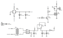
I am trying to interface a 380V DC 180 Watts DC Motor using 8051 controller. (Circuit Diagram Attached)
As per the circuit, the problem what i am facing is, As soon as i connect the system to 220V AC line, sometimes the bridge BR1 (KBP310) and Everytime 19N60 mosfet gets busted.
Can anybody please help me what the problem is with the circuit. Even checked for the shorts and Missing tracks, but everythin
i am going to use PWM to drive the motor.
Initially for testing i have just placed an LED with 100K 2 watts Resistor at the output to check it i get a proper output.
--- Updated ---

I Made a small Test, Using a 220V to 24V Transformer.
I Removed TR1 which is converting 220V AC to 12V AC and powering the controller.
and applied 24V AC to BR1 which is Powering the Motor.
and applied 12V DC from 220V to 12V DC Adaptor at the input of BR2 Pin AC-1 and AC-2. then the system is working perfectly, but the same when i connect to 220V AC, 19N60 Mosfet Explodes.
 

Attachments

  • 220DC Motor Drive.png
    220DC Motor Drive.png
    86.7 KB · Views: 138
Last edited:

Solution
Hi,

I guess you talk about
* conduction loss
only. But there additionally is
* switching loss.
It depends on switching frequency, load current and
Switch_on_time and switch_off_time.
This is the time when drain current flows, but voltage is not saturated (completely ON or OFF).
The higher the collector resistor value, the higher the switch_on_time, the higher the switching loss.

Your 19N60 Mosfet has a thermal resistance of about 40K/W without heatsink. This means you must not dissipate more than 3W.
When continously ON this means the current must not be higher than 2.8A (@380mOhm).

Switching a resistive load of 300 Ohm load at 300V gives 1A full current. And causes 0.38W.
But during switch ON there is tye worst case when the...
How do scope picture look: gate-source and drain-source?
Problem is you need a differential high voltage probe to measure signals in the bridge rectifier supplied circuit.

We are still missing the whole picture, e.g. how is the gate signal generated for the floating driver circuit.

Driving the MOSFET by a single transistor with pull-up resistor can work for 100k resistor but not hardly for motor load. A push-pull driver is required, can be gate driver IC or discrete transistor circuit.
Thanks all ,
I have done with it.
I changed the collector resistor of transistor to 22K and added a 0.1uF/450V Box Capacitor at mains input line and also replaced the 100uF/450V Electrolyte Capacitor.
The things are working properly.
 

Hi,

The collector resistor needs to be lower value to reduce switching loss.
Mind: usually gate drivers provide about an Ampere..
Otherwise you will get high power dissipation at the Mosfet.

Klaus
 

Hi,

The collector resistor needs to be lower value to reduce switching loss.
Mind: usually gate drivers provide about an Ampere..
Otherwise you will get high power dissipation at the Mosfet.

Klaus
But power dissipation at the mosfet depends upon load at load.
For Eg.
If I have 180 W of motor connected as a load, then the motor will itself dissipate around 180W of power to drive the motor.
 

Hi,

I guess you talk about
* conduction loss
only. But there additionally is
* switching loss.
It depends on switching frequency, load current and
Switch_on_time and switch_off_time.
This is the time when drain current flows, but voltage is not saturated (completely ON or OFF).
The higher the collector resistor value, the higher the switch_on_time, the higher the switching loss.

Your 19N60 Mosfet has a thermal resistance of about 40K/W without heatsink. This means you must not dissipate more than 3W.
When continously ON this means the current must not be higher than 2.8A (@380mOhm).

Switching a resistive load of 300 Ohm load at 300V gives 1A full current. And causes 0.38W.
But during switch ON there is tye worst case when the Mosfet has 300 Ohms. Then the drain current is 0.5A at a V_ds of 150V causing 75W of dissipation. This is about 200 times of the ON dissipation.
On every switching edge there is a time when it dissipates 75W ... no way around this.
Obviously this time with 75W dissipation should be short. Short switching time means high gate current.

In your case ... switching a 180W motor ... the switching loss will be much higher than the conduction loss.

***
BTW: you say a 180W motor dissipates this 180W.
This is not true.
Usually the 180W is the mechanical power that the motor can deliver.
None of the 180W will be dissipated as power within the motor.
But in the motor there will be some generated heat.
Winding loss, loss in the bearings, loss in the iron.
So don't be surprised if your motor draws more than 250W at rated power.
And starting current will be even higher.

Klaus
 
Solution
Status
Not open for further replies.

Part and Inventory Search

Welcome to EDABoard.com

Sponsor

Back
Top