Continue to Site

Welcome to EDAboard.com

Welcome to our site! EDAboard.com is an international Electronics Discussion Forum focused on EDA software, circuits, schematics, books, theory, papers, asic, pld, 8051, DSP, Network, RF, Analog Design, PCB, Service Manuals... and a whole lot more! To participate you need to register. Registration is free. Click here to register now.

DC Motor Inductance Measurement: 170mH too High?

Status
Not open for further replies.

chinuhark

Member level 5
Member level 5
Joined
Aug 16, 2014
Messages
88
Helped
1
Reputation
2
Reaction score
1
Trophy points
8
Visit site
Activity points
1,051
I am making a hysteresis current controller for a DC Motor for which I need it's inductance and resistance. It's specifications are:
220V(Armature), 4A(Armature), 0.75kW/1HP, 1500RPM.
I measure Resistance = 10.6 Ohms using a multimeter and applied AC voltage to the armature using a dimmer and used following relations:

Z = V/I

X = Root(Z^2-R^2 ) where R is ac Resistance = 1.6 times 10.6Ohms

L = X/(2*Pi*f )

I am getting Ra = 10.6Ohms and La = 170mH.
Aren't these values a bit too high or are they OK?
 

Formulas are correct, but I dont' understand what you measured.
R is the DC resistance (not the AC) and Z is the impedance you measured in AC [that is sqrt(R^2+X^2)]
Could you explain little bit better the procedure you followed ?
Which values, in ohm, you measured for Z and R ?
 

R was measured using a multimeter (~10 Ohms) and so the value it showed was the DC resistance (neglecting skin effect).
I used a dimmerstat and applied from 8V AC to about 25V AC to the armature and got currents of 0.15A to about 0.5A. The average impedance, (V/I = Z) I got after averaging 6-7 readings was about 56 Ohms. So Z = Rac^2 + X^2. As the resistance offered by a conductor to AC current is about 1.6 times that in the case of DC current (due to skin effect) Rac = 1.6*10 Ohms = 16 Ohms. This gives X^2 = 56^2 - 16^2 = ~58 Ohms. Thus L = ~170mH.
P.S. Even if I use R = 10 Ohms, the value of L will be much higher.
 

A winding receives power for only a fraction of a second. On the order of 1/100 sec.

Current starts at 0A. It ramps up to a level governed by the L/R time constant.

Then the brushes move on to the next winding.

Current never reaches maximum amperes in normal operation. Only if you stall the motor, would you get maximum current through a winding. The aim is to avoid letting this happen, of course.
 

What I don't understand is whether such a value of inductance is ok for a motor of this size as I can't find typical inductance values for DC motors anywhere and the few I found in Numerical problems in books never have a inductance greater than 50-60mH...
 

"This gives X^2 = 56^2 - 16^2 = ~58 Ohms." XXX, should be 53 - slight difference :) One thing its a DC motor, so what configuration is it? series, parallel wound or permanent magnet? Not being an expert but a few hundred turns wound on a high permeabilty core, it would seem to be in the right order. The running value at 4A would be lower then your measured value (saturation).
Frank
 

From your calculation the AC frequency is 50 Hz, then the skin effect is negligible.
So R=10 ohm, Z=56 ohm, then XL=55 ohm that means, at 50 Hz L=175 mH. I Think it's quite high but it is a possible value.
However the above equations are valid only if your AC waveform is a sinewave. For instance if you used a simple light dimmer this is not true.
 

I used a dimmerstat (autotransformer), so wave has to be sine and that shouldn't be an issue.
Is there any other method for greater accuracy, or should I go ahead with this value?
 

What I don't understand is whether such a value of inductance is ok for a motor of this size as I can't find typical inductance values for DC motors anywhere and the few I found in Numerical problems in books never have a inductance greater than 50-60mH...

Motor manufacturers are motivated to keep a lot of things secret, for business reasons.

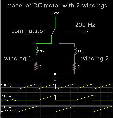
Here is my conceptual model of a DC motor.

Supply current alternates between two windings. Two should be sufficient to portray the action (conceptually speaking).

1086290600_1415843837.png


Each winding connects to power for 1/200 second. This time-length is an estimate, calculated from 25 rotations per second (1500 RPM), and eight (just to choose a number) windings.

To get 750W of power at 220V, calculates to a current flow of 3.4 A avg. However there are not that many amperes coming from the supply.

To obtain greater current flow, we reduce the inductance. Therefore your windings might in fact have a lower inductance than 170mH.
 

What type of DC motor it is?
Series, shunt, compound, permanent magnet?

Regardless, your measured values appear to be quite high for a DC motor.

According to the DC motor's equation:
Terminal voltage: V = LδI/δt + Ia*Ra + kb*ω
and to a first order approximation Torque: τ = kt*I

and you solve for speed as a function of torque, keeping the terminal voltage constant, you will find that changes in the load torque will cause a very significant change in the motor speed, and depending on the moment of inertia, the system could even become unstable.
 
Last edited:

It is a seperately excited motor with A-AA and F-FF terminals coming out. The measurements were done on the armature winding(that's not the issue)

Yesterday I used a Scope to again measure the inductance. I measured the phase difference between the Voltage across the the armature winding and current through it. It was 76.5 degrees. Resistance Ra is 10.5 Ohms and using 1.6times the value and tan(Φ) = X/R I got L = 100.0mH
I had gotten the exact same value 100.0mH with an LCR meter in our Lab but the person who gave it to me said that it 'might' be broken so accuracy was not guaranteed. After getting 100mH I concluded it was in fact broken but this method is giving the same result.

So....should I go with 100mH and is it a possible value as time constant L/R becomes 0.1/10 = 10ms. Can it be correct?
 

My electrical machines textbook mentions typical armature time constants of 20 to 60 ms. As the book is more dedicated to large machines, 10 ms sounds reasonable for a 750 W motor.
 

Thanks. Exactly what I wanted. A confirmation that it is not way off as compared to what it should be for a machine it's size...
 

Status
Not open for further replies.

Similar threads

Part and Inventory Search

Welcome to EDABoard.com

Sponsor

Back
Top