jayanth.devarayanadurga
Banned
- Joined
- Dec 4, 2012
- Messages
- 4,280
- Helped
- 822
- Reputation
- 1,654
- Reaction score
- 791
- Trophy points
- 1,393
- Location
- Bangalore, India
- Activity points
- 0
Yes. you are right. Use TIP transistors.
Follow along with the video below to see how to install our site as a web app on your home screen.
Note: This feature may not be available in some browsers.
You said that your motor is 12 V 300 mA then why do you want to use 7805 for motors? You do't need any regulator for motor. If yo want then you have to use 7812. If you want to use TIP transistor then I think TIP 50 or TIP 100 will do. https://www.futurlec.com/TransPowerTIP.shtml You have to connect two transistors for each motor. L293 is enough for you but if it is heating even after replacing the device then put a good heatsink and see. Try using ULN2803A between l293D and motor. It has 8 inputs and 8 outputs and each channel is 500 mA max.
No!
The 2803 can only sink current so it won't work in a H-Bridge configuration. It also has lower current capability than the L293. Although each output of the 2803 can sink 500mA, the total package can't handle 4 Amps!
My comment on using two 7805s for the logic supply was meant to warn of the danger of the one providing the control signals powering up before the one providing the VCC logic supply. Feeding both from the same 7805 prevents that happening.
Brian.
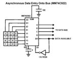
The problem is that when the keys are released, the outputs of the 74C922 are tri-stated (disconnected inside the IC). With nothing driving the '154 it's inputs are floating. You should add a pull-up resistor to each of the data lines entering the '154 so when no key is pressed the lines are pulled high. This will ensure that only output 15 is low and all the other outputs are high. As you are not using output 15 it should be safe to use it as a default 'no key' output.
Brian.
Can you confirm which IC you are actually using. Your text refers to 74923 which as far as I know does not exist. There is a 74C923 which is a 20 key encoder but your schematics show a 74C922 which is a 16 key encoder. I'm just wondering if you have the wrong pin diagram for the IC.
Brian.
Thanks.
The supply voltage is OK and the oscllator voltage is reasonable but it isn't reporting that a key is pressed at all.
I suspect the values of capacitors you are using are simpy too high. You have the scanning rate set too slow for it to function and the debiounce time is set to around one second. This means if it works at all, you may have to wait for several seconds for a key press to be detected and the key would have to be held down for more than one second before being reported.
I suggest changing the values of the oscillator capacitor (C2) to 100nF and the debounce capacitor to 1uF and try again. I also suggest you wire a capacitor of about 100nF across pins 10 and 20 to help the oscillator remain stable.
Brian.
There is only one more thing to try:
Disconnect the inverter from pin 14. Connect pin 14 directly to ground.
Using 100nF and 1uF for the capacitor values, try pressing a few keys and see what comes out of pins 15 to 19. The data on these pins should be the binary number of the key you pressed and it should stay there until you press another key.
If that doesn't work, I'm afraid your 74C923 is dead :|
Brian.
 Receiving side code

#include <16F877A.h>
#device *= 16
#fuses HS, NOWDT, NOPROTECT, NOLVP, PUT
#fuses NOBROWNOUT, CPD, NODEBUG, NOWRT
#use delay(clock=10MHz)
#use rs232(baud=1200, rcv=PIN_C7, bits=8, parity=N)

#include <lcd.c>
void receive();
void main()
{
 while(1)
{
 if(dataavailable!=false)
 receive();
}
 }

receive()
{
 byte c;
 lcd_init();
 lcd_putc("\f");
 while(true)
 {
 c=getc();
 switch(c)
 case 1;
           action1;
           break;
.................
case 32;
         action32;
         break;
 printf(lcd_putc,"\fRx Data = %u",c);
 delay_ms(100);
}
}


Transmitting side code

#include <16F877A.h>
#device *= 16
#device adc=8
#fuses HS, NOWDT, NOPROTECT, NOLVP, PUT
#fuses NOBROWNOUT, CPD, NODEBUG, NOWRT
#use delay(clock=10MHz)
#use rs232(baud=1200, xmit=PIN_C6, bits=8, parity=N)

#include <lcd.c>

void main()
{
 byte s=0;
 lcd_init();
 lcd_putc("\f");

 while(true)
 {
 s =  readswitches();
 lcd_gotoxy(1,1);
 printf(lcd_putc, "\fTx Data = %u" s);
 putc(s);
 delay_ms(100);
 }
}
WHen you input switch operates it bounces and the TTL input is floating at threshold of 1.3V. Any rapid noise on this input will cause shoot-thru shorting of the drivers.
Any change in directions will also cause motor/generator back EMF to dump into drivers.
Therefore use 4K7 to 10K pullup on all TTL inputs at switches and 0.1uF to ground.
If you are sure a 74C923 will do what you want, I can write a simple program for an inexpensive PIC to emulate it's actions. It would be simpler than the 74C923 circuit because I can make the enable signal programmable and do the debunce in a software routine. I'm thinkng of a 16F628A as the processor because it has sufficient pins and an on-board clock, can you buy them in your locality?
Brian.
Thanks for Your concern... and i need that but i have PIC16F877A.. i already did my hobby circuits with that.. so i am little bit familiar in that.. and is my program will work that i post in #34... please tell me that also... thanks once again... very much thanks... i need to work on my own but also give me the program i will post my one also and please check that whether it will work...